Retaining device

a technology of retaining device and carrier plate, which is applied in the directions of pedestrian/occupant safety arrangement, vehicle safety arrangement, transportation and packaging, etc., can solve the problems of increasing reducing the rigidity of the device, and requiring more welding engineering. cost and complicated,

Inactive Publication Date: 2006-08-24
TAKATA EURO VEHICLE SAFETY TECH
View PDF2 Cites 12 Cited by
  • Summary
  • Abstract
  • Description
  • Claims
  • Application Information

AI Technical Summary

Benefits of technology

[0015] The retaining device is preferably essentially of elongated design and is provided with angled portions. As a result, it can be matched to the shape of the motor-vehicle component. The receiving region of the structural element is preferably shaped in such a manner that there is space for receiving a screw connection, for example, between the structural element and retaining device. In addition, the deformation causes the rigidity of the device to be increased.
[0016] The production of the retaining device proves to be cost-effective if, preferably, the hook is of integral design with the retaining device. The preferred material for simple and cost-effective production is sheet metal. However, the retaining device may also be formed as a metal die casting or as a plastic injection molding with inserts. Castings and moldings are very cost-effective to produce. A further advantage of a plastic injection molded part resides in its low weight.

Problems solved by technology

Costly and complicated welding engineering has to be used in order to install this carrier plate.
In addition, it is not possible to mount the air-bag module and carrier plate in one working step.
If the side strut of the seat does not have a round rod shape and is instead designed as a flat metal plate, welding on the carrier plate and mounting of the air-bag module is even more difficult.

Method used


Image

  • Retaining device
  • Retaining device
  • Retaining device

Examples


Embodiment Construction

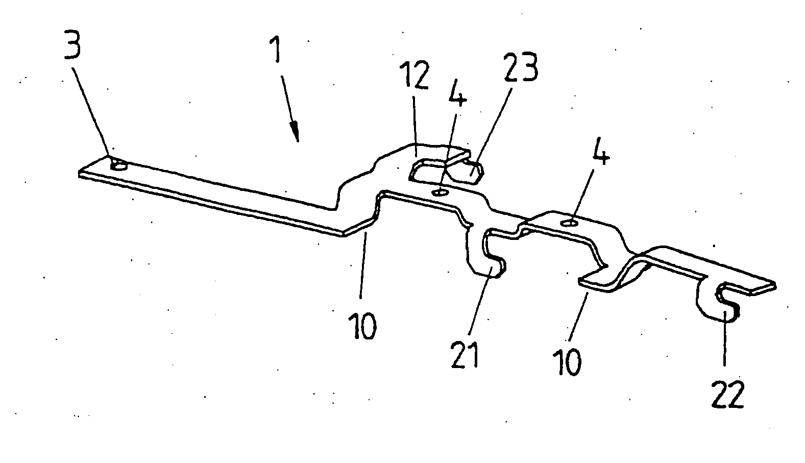
[0036]FIG. 1 discloses a first embodiment of a retaining device 1 according to the invention. The retaining device 1 is designed as an elongated metal plate and in addition to a plurality of angled regions has three hooks 21, 22, 23 for fitting into elongated holes (not illustrated) of a motor-vehicle component. A hook 23 may be formed on a side arm 12 of the retaining device 1.

[0037] An opening 3 which is formed in the edge region of the retaining device may be used in conjunction with the hooks 21, 22, 23 for fastening the device 1 to the motor-vehicle component by means of a screw connection or another method of fastening.

[0038] Furthermore, installation openings 4 are provided and can be used to fasten an air bag or another structural element to the retaining device 1, for example via a screw connection. Other methods of fastening may also be used.

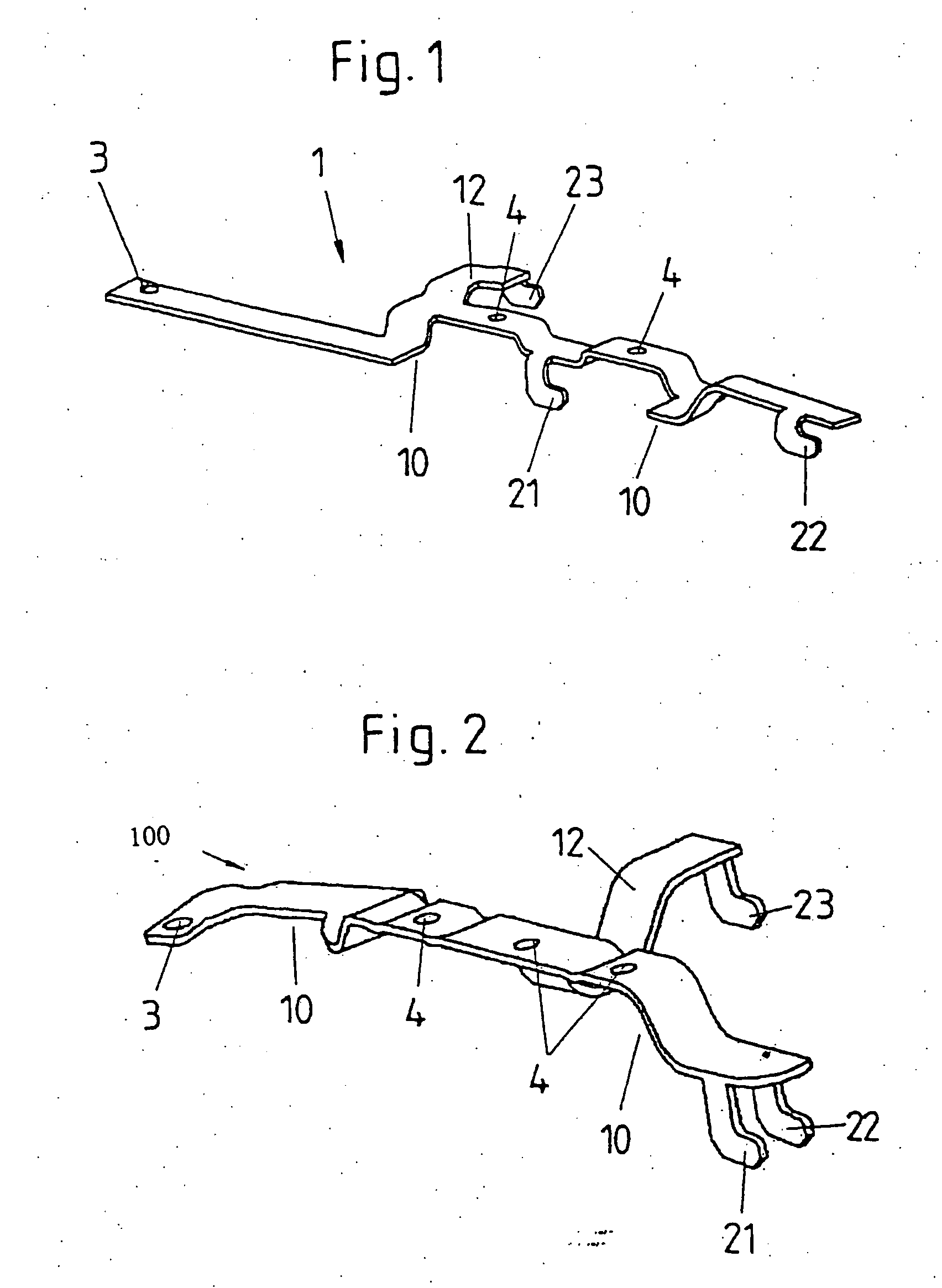
[0039]FIG. 2 discloses a retaining device 1 which is similar to the exemplary embodiment of FIG. 1. The arrangement of the hooks 2...


PUM


Abstract

A retaining device for an airbag module is provided. At least a portion of the airbag module is connected to the retaining device. The retaining device may include a hook and an element for fastening the device to a motor vehicle component. The component may be, for example, a vehicle seat or a vehicle door. The element for fastening the device to the motor vehicle component may include an opening and fastener arrangement or a clip type arrangement.

Description

[0001] This application is a divisional application of U.S. patent application Ser. No. 10 / 024,516, filed Dec. 21, 2001.BACKGROUND [0002] The invention relates to a retaining device for at least one structural element. In particular the invention relates to a retaining device for an airbag module. [0003] Among other things, restraint systems for people in motor vehicles include side air bags. Side air bags are usually placed at different points along the longitudinal sides of the vehicle. Currently, there are a number of options for fitting the air bags to the vehicle. For example, the air bag may be integrated into a vehicle door or a vehicle seat. The side air bag may be integrated in the backrest of the seat, and can be fixed to a side strut of the backrest. [0004] U.S. Pat. No. 5,752,714 (incorporated by reference herein) discloses an option for fastening an air bag to a vehicle backrest. In this, a carrier plate is welded to the round, rod-like strut of the backrest and the air...

Claims


Application Information

Patent Timeline
Patent Type & Authority Applications(United States)
IPC IPC(8): B60R21/217B60R21/20B60R21/207
CPCB60R21/207
Inventor AULBACH, ALEXANDER
Owner TAKATA EURO VEHICLE SAFETY TECH
Why Eureka
Try Eureka