Structure of far infrared radiator and projection head of the same

Inactive Publication Date: 2005-10-20
TSAI LI FA
View PDF4 Cites 0 Cited by
  • Summary
  • Abstract
  • Description
  • Claims
  • Application Information

AI Technical Summary

Benefits of technology

[0005] To resolve the drawbacks of the conventional design, a covering layer is coated on a projection head of an infrared radiator, such that the near infrared light with higher energy is blocked, while only the far infrared light with lower energy passes through. Therefore, the patient under treatment only feels a warm temperature. Application of the fomentation for a long period of time will not burn the skin or cause deformation of crystals of eyes of the patient.
[0006] The covering layer is mixed by ceramic powders, high-temperature adhesive and water to cover a high-resistant wiring (nickel / chromium). When the projection head is conducted to a source power to generate a visible infrared light beam, the near infrared light that has a higher energy is blocked by the covering layer. Therefore, the patient under thermal treatment will not feel excessive heat.

Problems solved by technology

Further, the crystal of eyes will be deformed or damaged by radiation of near infrared light.
In the conventional medical equipment providing infrared treatment, the near infrared light has not been effectively filtered or blocked.
Therefore, it is inevitable to harm the patient due to the high thermal energy.

Method used


Image

  • Structure of far infrared radiator and projection head of the same
  • Structure of far infrared radiator and projection head of the same
  • Structure of far infrared radiator and projection head of the same

Examples


Embodiment Construction

[0017] Reference will now be made in detail to the preferred embodiments of the present invention, examples of which are illustrated in the accompanying drawings. Wherever possible, the same reference numbers are used in the drawings and the description to refer to the same or like parts.

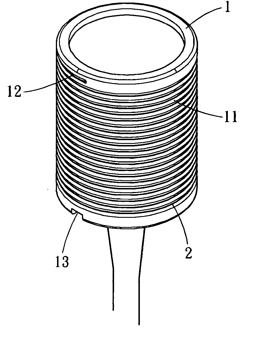
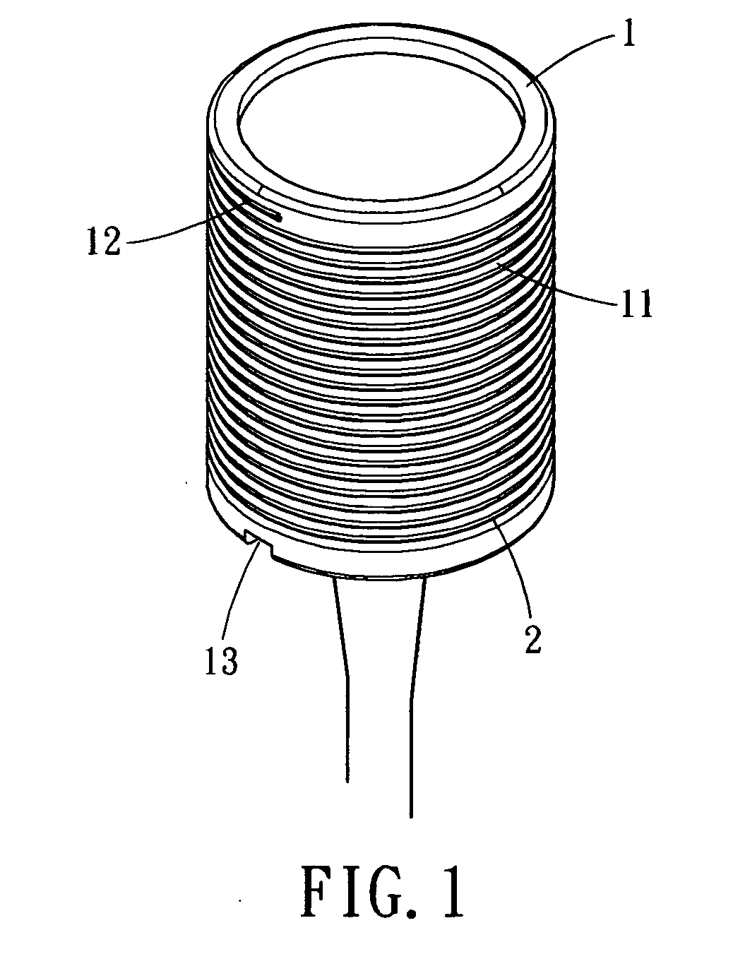
[0018]FIG. 1 illustrates a perspective view of a projection head of an infrared radiator. As shown, the projection head includes a frame 1, a high-resistant wiring 2 winding around the head frame 1, and a covering layer 3 coated on the frame 1 so as to wrap the high-resistant wiring 2 therein. When the high-resistant wiring 2 is conducted to a source power, an infrared beam containing visible components of light is generated. The covering layer 3 blocks the near infrared portion of the infrared light and only allows the far infrared portion of the infrared light to pass. Therefore, the near infrared light with higher energy will not be incident on the human body. The injury caused by high-energy ne...


PUM


Abstract

A structure improvement of a far infrared radiator and a projection head thereof is disclosed. A covering layer made of ceramic powders, high-temperature adhesive and water is coated on a frame wound with a high-resistant wiring (nickel-chromium wire). When a source power is supplied from the lamp base to generate infrared radiation containing visible range of light, the covering layer blocks the near infrared radiator carried by the infrared radiation, such that only the far infrared radiator with lower thermal energy can pass through to radiate the lampshade. The lampshade then reflects the far infrared radiator upon the skin of the patient. Therefore, during thermal treatment, the patient will not subjected to excessive heat and high temperature.

Description

BACKGROUND OF THE INVENTION [0001] The present invention relates in general to a structure improvement of a far infrared radiator and a projection head thereof, and more particularly, to a far infrared radiator which radiates far infrared light with lower energy, such that the patient under thermal treatment will not feel the heat. [0002] Far infrared light is decoupled from infrared light. The components of infrared light include near infrared light, mid infrared light and far infrared light. The far infrared light having longer wavelength and lower energy is most applicable to human bodies, animals and vegetables. Far infrared light is a type of electromagnetic wave, and the human body is an organic entity, which is also a radiator of far infrared. Therefore, the far infrared light has very sufficient warming effect to human body. In addition, the far infrared light can penetrate deep into the skin and the subcutaneous tissues of the human body. It thus accelerates blood circulati...

Claims


Application Information

Patent Timeline
IPC IPC(8): H01K7/00H05B3/00
CPCH05B2203/032H05B3/0085
Inventor TSAI, LI-FA
Owner TSAI LI FA
Why Eureka
Try Eureka