Assembly jig including a fixture for a perforated panel

a perforated panel and fixture technology, applied in the field of assembly jigs, can solve the problems of requiring additional time and labor for mounting the wiring jigs, and the inability to arrange the wiring jigs in the desired position on the perforated panel

Inactive Publication Date: 2001-10-30
SUMITOMO WIRING SYST LTD
View PDF13 Cites 19 Cited by
  • Summary
  • Abstract
  • Description
  • Claims
  • Application Information

AI Technical Summary

Problems solved by technology

Thus, it can be impossible to arrange the wiring jigs in the desired position on the perforated panel.
In addition, although it is considered that the mounting position can be adjusted after mounting the wiring jigs by adopting a mount

Method used


Image

  • Assembly jig including a fixture for a perforated panel
  • Assembly jig including a fixture for a perforated panel
  • Assembly jig including a fixture for a perforated panel

Examples


Embodiment Construction

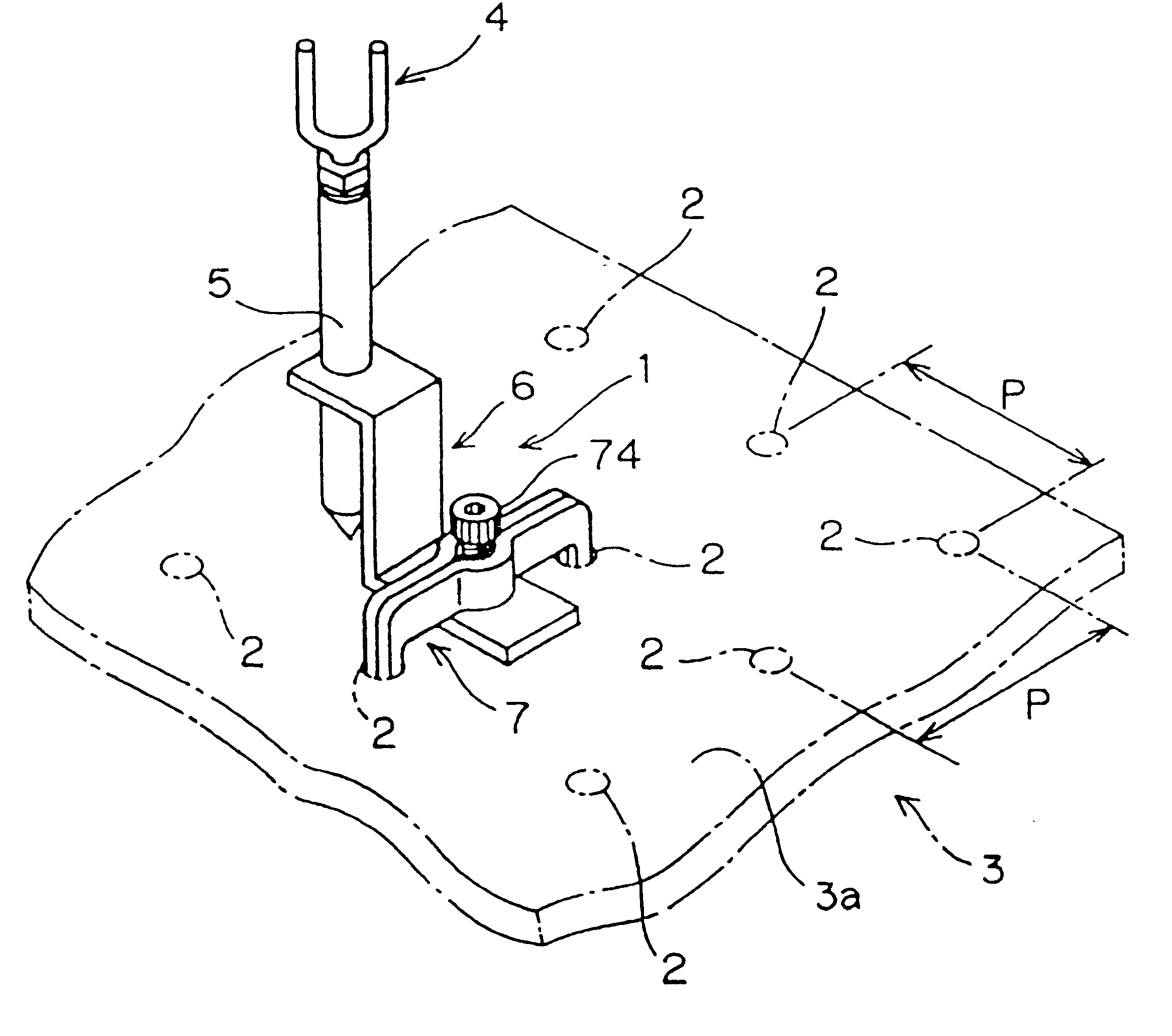
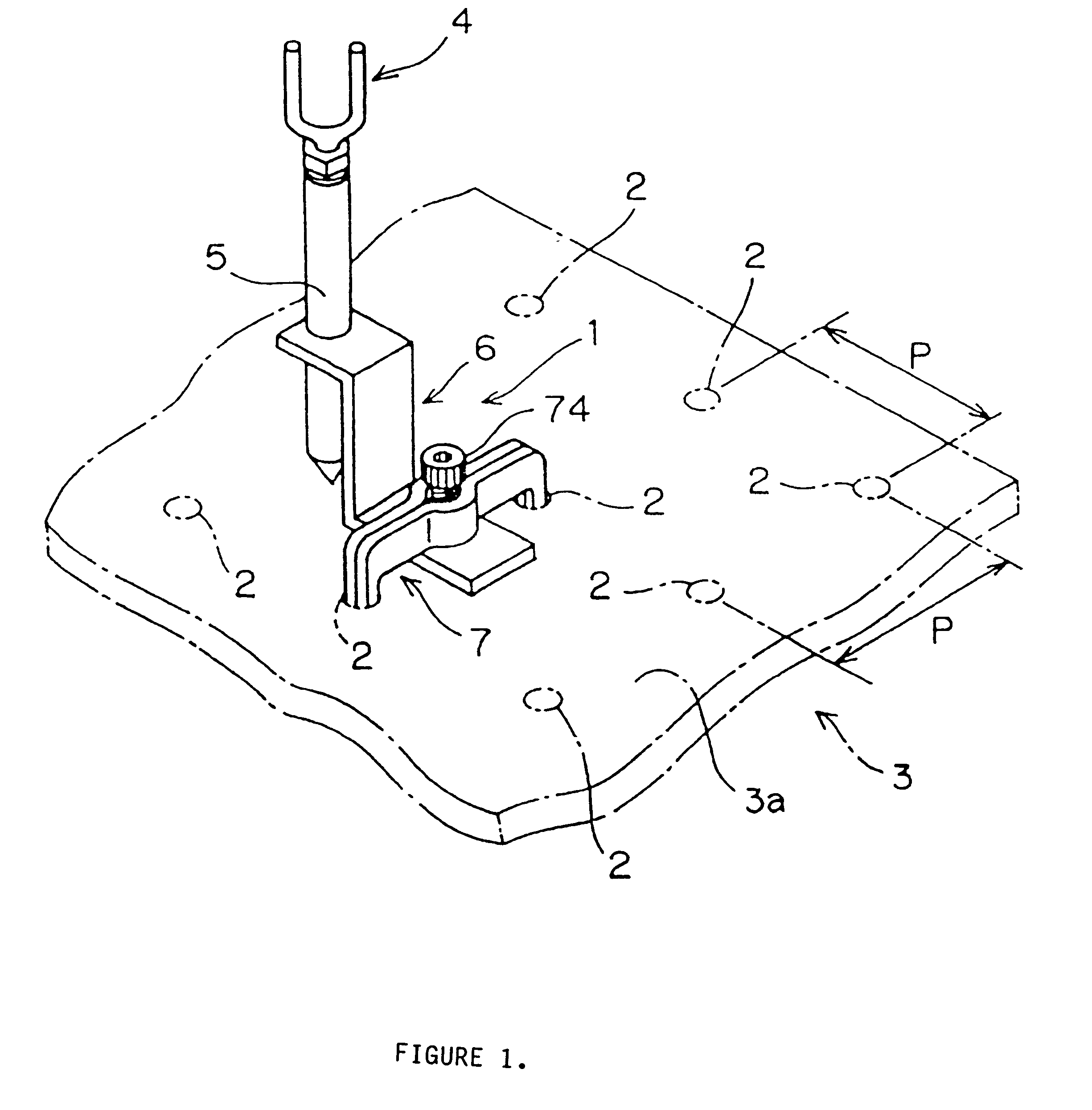
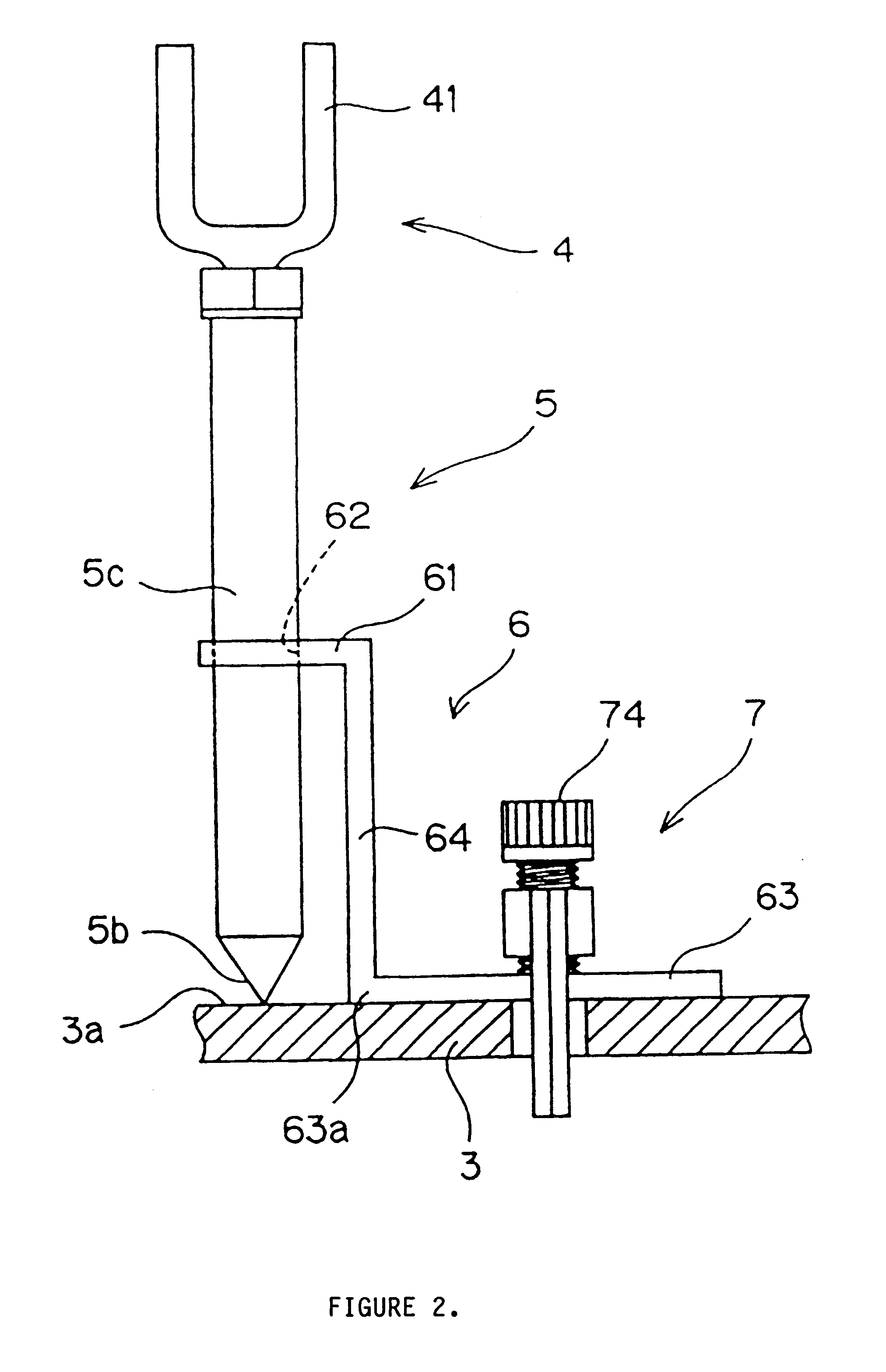
As illustrated in the accompanying drawings, FIG. 1 represents a perspective view showing an embodiment of the invention in which one wiring jig 1 for an assembly jig is mounted on a perforated panel 3. The wiring jig 1 is provided with a cable receiving area 4 supported by a pillar 5 from the lower side. The pillar 5 is supported by a crank-shaped supporting member 6 fastened to the surface 3a of the perforated panel 3 by a pressing member 7.

The perforated panel 3 is formed as a flat board having a predetermined thickness and is, for example, constructed from a metallic plate, although any suitable material may be used. A number of generally circular mounting holes 2 are provided in the board which penetrate through the top surface 3a and bottom surfaces 3b of the flat board. The mounting holes 2 are aligned in two directions at right angles to each other, e.g., longitudinal and transverse directions of the board. In each direction, the holes 2 are arranged at predetermined regular...


PUM


Abstract

A wiring jig is provided with a cable receiving area which receives cables. A crank-shaped supporting member supports a pillar which supports the cable receiving area. A pressing member having a pair of locating feet is provided with a pressing screw. Tightening the pressing screw of the pressing member fastens the supporting member to a perforated panel. Loosening the pressing screw allows the supporting member to rotate and/or slide so that the pillar can be installed at any desired position without being limited by the position of mounting holes pre-formed with a predetermined spacing in a perforated panel which receive the pair of locating feet of the pressing member.

Description

1. Field of the InventionThe present invention relates to an assembly jig for wire harness to be fastened to a perforated panel In which multiple holes are formed and arranged with predetermined spacing, and to a perforated panel fixture for fastening the assembly jig.2. Description of Background InformationWhen assembling a wire harness, a wiring base board is used on which a number of wiring jigs are provided. Consequently, holes are formed at predetermined positions in the base board and a lower end of the wiring jig is fitted into the holes and fastened with bolts on both the top and the bottom surfaces of the perforated board. The board mounted with the wiring jig becomes the exclusive article for assembling the particular kind of wire harness.On the other hand, since the wire harnesses follow a trend of diverse / small batch production and require assembling for test production, a wiring board which allows common use for assembly of different kinds of wire harnesses is highly de...

Claims


Application Information

Patent Timeline
IPC IPC(8): B60R16/02H05K13/06H01B13/012
CPCB60R16/0207Y10S269/903Y10S269/90
Inventor OTA, NORIOKATO, HAJIME
Owner SUMITOMO WIRING SYST LTD
Why Eureka
Try Eureka