Plate for heat exchange and heat exchange unit

a technology of heat exchange and heat exchange unit, which is applied in the direction of lighting and heating apparatus, laminated elements, and stationary conduit assemblies, etc., can solve the problems of deteriorating heat transfer performance, unfavorable variation in the distance between the plates, and the use of heat exchange fluid, etc., to achieve sufficient heat transfer performance relative, excellent heat transfer property, and flexible use

Inactive Publication Date: 2005-07-14
XENESYS
View PDF3 Cites 7 Cited by
  • Summary
  • Abstract
  • Description
  • Claims
  • Application Information

AI Technical Summary

Benefits of technology

[0009] An object of the present invention, which was made to solve the above-mentioned problems, is therefore to provide a heat exchange plate, which is provided on it surface with a pattern of irregularity properly formed, has flexibility in use in the flowing system, and permits to ensure a sufficient heat transfer performance relative to fluids, thus providing an excellent heat transfer property, as well as a heat exchange unit in which such a heat exchange plate and the other plates are combined to provide a determined heat transfer property.
[0013] According to the first aspect of the present invention, the heat exchange plate is formed of the metallic plate member having the pattern of irregularity that includes the main protrusions and the intermediate protrusions provided on the plate member. Combining such a heat exchange plate with the other heat exchange plates so that these plates face each other at the same side and the tops of the main protrusions of the plate come into contact with the corresponding tops of the main protrusions of the other plate, or so that these plates face each other at the same other side and projections between the adjacent two intermediate protrusions of the plate come into contact with corresponding projections of the other plate, provides a gap between the adjacent two plates. The above-mentioned gap has a dimension corresponding to the pattern of irregularity of the plates, in which a unit of the similar pattern of irregularity is repeated in two directions that are perpendicular to each other, thus providing linear passages extending in the above-mentioned two directions so as to cross each other at right angles. More specifically, each of the linear passages extending in the direction includes expanded areas and throat areas that are placed alternately in the same direction, on the one hand, and the linear passage extending in the perpendicular direction to the above-mentioned direction includes expanded areas and throat areas that are placed alternately in the same perpendicular direction, in the similar manner. Using the thus assembled plates so that the flowing direction of the heat exchange fluid coincides with the linear passage or is perpendicular thereto can impart substantially the same behavior to the heat exchange fluid, irrespective the flowing system of the heat exchange fluid, i.e., any one of the parallel flowing system, the counter-flowing system and the cross flowing system. As a result, it is possible to perform a smooth heat transfer at a low pressure loss to make an effective heat exchange, even when the heat exchange fluids are combined in any manner in their flowing directions, thus providing a high degree of freedom in design of the heat exchanger and becoming excellent in general purpose use. In addition, the heat exchange fluid ca flow freely in the above-mentioned two directions along the plate, and the constant heat transfer property can be obtained, irrespective of the flowing direction of the heat exchange fluid. It is therefore possible to cause the heat exchange fluid to spread over the entire area of the plate so that such an entire area can serve as an effective heat transfer section, thus increasing remarkably an amount of heat transfer per area and achieving a high performance. Further, the strength of the assembled plates can be improved remarkably by bringing the protrusions of the plate into contact with the corresponding protrusions of the other plate, and it is therefore possible to keep the distance between the adjacent two plates constant, even when there exists a large difference in pressure between the heat exchange fluids, thus enhancing a pressure-resistant property.
[0015] According to the second aspect of the present invention, the plate member has the pattern of irregularity in which the ridgelines of the main protrusions extend in parallel with or perpendicular to the side edges of the plate member. Placing the plates having such a pattern of irregularity so that the side edge of the plate coincides with a horizontal direction or vertical direction provides areas between the intermediate protrusions and the foot portions, each of which areas extends obliquely relative to the horizontal or vertical direction. As a result, the heat exchange fluids introduced into the combined plates flows in the oblique direction, and repeats divergence and confluence to spread over every area of the plate. It is therefore possible to cause the heat exchange fluid to spread over the entire area of the plate to facilitate the heat transfer between the heat exchange fluids and improving the heat exchange rate.
[0019] According to the third aspect of the present invention, the heat exchange plate is formed of the metallic plate member having the pattern of irregularity that includes the protrusions and the recess portions provided on the plate member. Combining such a heat exchange plate with the other heat exchange plates so that these plates face each other at the same side and the tops of the protrusions of the plate come into contact with the corresponding tops of the protrusions of the other plate. The above-mentioned gap has a dimension corresponding to the pattern of irregularity of the plates, in which a unit of the similar pattern of irregularity is repeated in two directions that are perpendicular to each other, thus providing linear passages extending in the above-mentioned two directions so as to cross each other at right angles. More specifically, each of the linear passages extending in the direction includes expanded areas and throat areas that are placed alternately in the same direction, on the one hand, and the linear passage extending in the perpendicular direction to the above-mentioned direction includes expanded areas and throat areas that are placed alternately in the same perpendicular direction, in the similar manner. Using the thus assembled plates so that the flowing direction of the heat exchange fluid coincides with the linear passage or is perpendicular thereto can impart substantially the same behavior to the heat exchange fluid, irrespective the flowing system of the heat exchange fluid, i.e., any one of the parallel flowing system, the counter-flowing system and the cross flowing system. As a result, it is possible to perform a smooth heat transfer at a low pressure loss to make an effective heat exchange, even when the heat exchange fluids are combined in any manner in their flowing directions, thus providing a high degree of freedom in design of the heat exchanger and becoming excellent in general purpose use. In addition, the heat exchange fluid ca flow freely in the above-mentioned two directions along the plate, and the constant heat transfer property can be obtained, irrespective of the flowing direction of the heat exchange fluid. It is therefore possible to cause the heat exchange fluid to spread over the entire area of the plate so that such an entire area can serve as an effective heat transfer section, thus increasing remarkably an amount of heat transfer per area and achieving a high performance. Further, the strength of the assembled plates can be improved remarkably by bringing the protrusions of the plate into contact with the corresponding protrusions of the other plate, and it is therefore possible to keep the distance between the adjacent two plates constant, even when there exists a large difference in pressure between the heat exchange fluids, thus enhancing a pressure-resistant property.
[0021] According to the fourth aspect of the present invention, two kinds of plates, i.e., the first set of plates and the second set of plates having the ridgelines extending in the different direction from the extending direction of the ridgelines of the first set of plates are assembled in an appropriate combination into a unit, so as to provide combined properties of the different heat exchange properties of the two kinds of plates, for a general structure of the unit. It is therefore possible to adjust the heat exchange properties for the general structure of the unit by combining the two kinds of plates in a different manner, thus providing relatively easily the desired heat exchange properties. Consequently, there can be provided a heat exchanger, which has optimum properties and an excellent heat exchange efficiency in accordance with a kind, state and amount of the heat exchange fluid, as well as an actual use of the heat exchanger.

Problems solved by technology

However, a high pressure of the heat exchange fluid flowing between the plates may cause deformation of the gasket member, thus disabling an appropriate separation of the fluids from being ensured or leading to an unfavorable variation in distance between the plates.
In such a case, an effective heat exchange may not be carried out, thus causing a problem.
In view of these facts, the conventional heat exchanger involves a problem that the heat exchange fluids can be utilized only in a pressure range in which the gasket member withstands.
When the plates having the pattern of irregularity, which has been optimized exclusively for the flowing system to be applied originally, are applied to the different flowing system, variation in flowing conditions may occur to deteriorate the heat transfer performance, thus leading to a lower heat exchange efficiency and increase in pressure loss.
However, the inflow divergent area and the outflow condensation area having patterns of irregularity, in which importance is placed generally on the guiding performance for the fluids, do not provide a sufficient heat transfer performance.
The excellent heat transfer performance cannot be provided by these areas, with the result that an effective area utilized for heat transfer is relatively small to the total area of the plate, thus causing waste in space of occupancy and cost.

Method used


Image

  • Plate for heat exchange and heat exchange unit
  • Plate for heat exchange and heat exchange unit
  • Plate for heat exchange and heat exchange unit

Examples


first embodiment

of the Present Invention

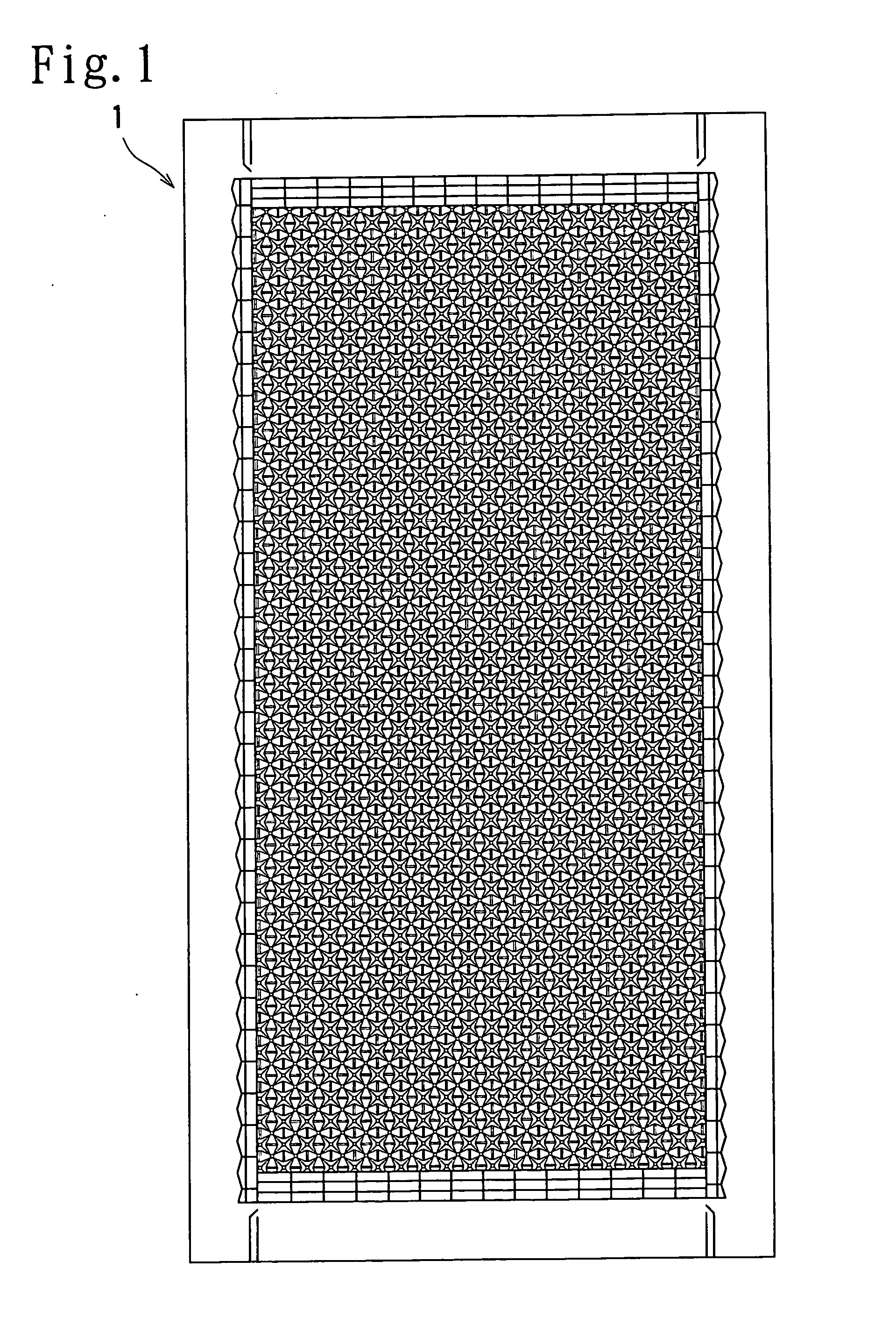
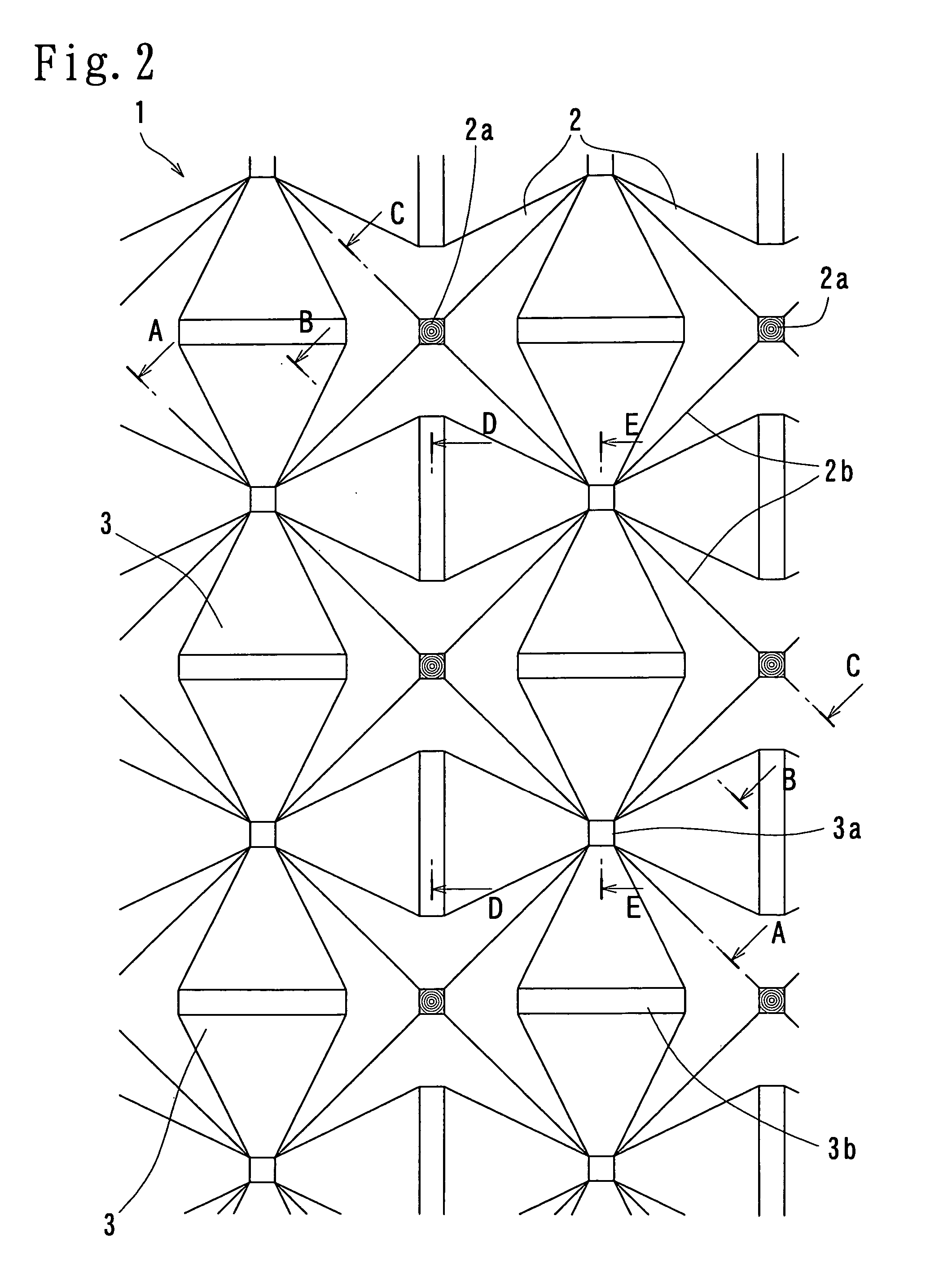
[0033] Now, the first embodiment of the present invention will be described in detail below with reference to FIGS. 1 to 5(B). FIG. 1 is a schematic structural view of a heat exchange plate according to the first embodiment of the present invention. FIG. 2 is an enlarged plan view of an essential structure of the heat exchange plate according to the first embodiment of the present invention. FIG. 3(A) is a cross-sectional view cut along the line A-A in FIG. 2, FIG. 3(B) is a cross-sectional view cut along the line B-B in FIG. 2 and FIG. 3(C) is a cross-sectional view cut along the line C-C in FIG. 2. FIG. 4(A) is a cross-sectional view cut along the line D-D in FIG. 2 and FIG. 4(B) is a cross-sectional view cut along the line E-E in FIG. 2. FIGS. 5(A) and 5(B) are descriptive views illustrating gaps formed between a pair of combined heat exchange plates according to the first embodiment of the present invention and the other gaps formed between the other pair...

second embodiment

of the Present Invention

[0044] Now, the second embodiment of the present invention will be described in detail below with reference to FIGS. 6 and 7. FIG. 6 is a schematic structural view of a heat exchange plate according to the second embodiment of the present invention. FIG. 7 is a descriptive view illustrating a flow of a heat exchange fluid in the combined heat exchange plates according to the second embodiment of the present invention.

[0045] As shown in FIGS. 6 and 7, the heat exchange plate 10 according to the second embodiment of the present invention has the pattern of irregularities with the main protrusions 11 and the intermediate protrusions 12 in the same manner as the above-described first embodiment of the present invention. However, the heat exchange plate 10 according to the second embodiment differs from the first embodiment in that the ridgelines 14 of the main protrusions 11 extend in parallel with or perpendicular to the side edges of the heat exchange plate 10...

third embodiment

of the Present Invention

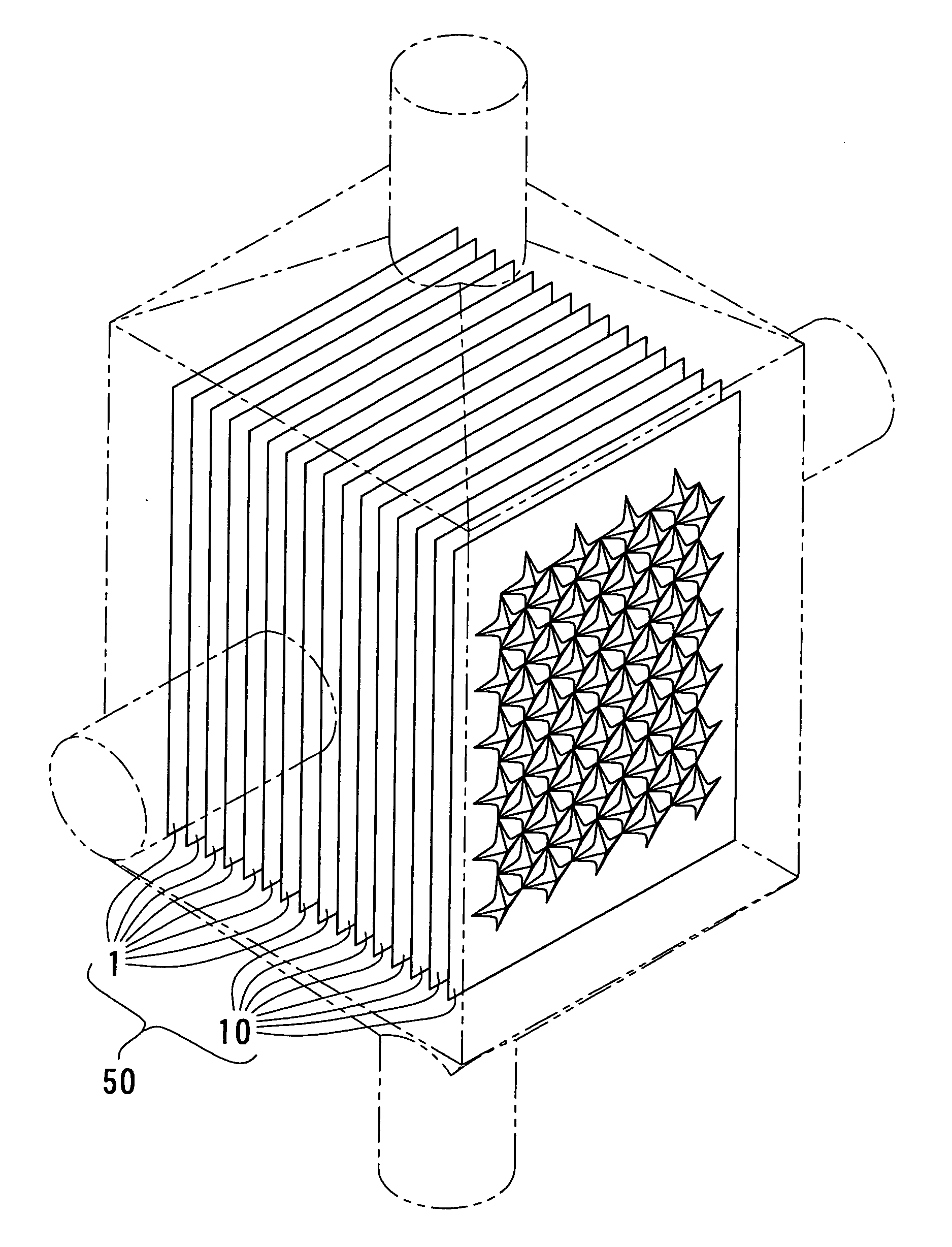
[0051] Now, the third embodiment of the present invention will be described in detail below with reference to FIG. 11. The third embodiment describes a heat exchange unit into which the above-described heat exchange plates of the present invention are assembled so as to be placed in parallel with each other. FIG. 11 is a schematic structural view of the heat exchange unit according to the third embodiment of the present invention.

[0052] As shown in FIG. 11, the heat exchange unit 50 has a structure in which a predetermined number of the first heat exchange plates according to the first embodiment and a predetermined number of the second heat exchange plates according to the second embodiment are combined with each other. More specifically, the first heat exchange plates each having the pattern of irregularities in which the ridgelines 2b of the main protrusions 2 intersects any one of the sides of the plate having the rectangular shape at an angle of 45 degr...


PUM


Abstract

A heat exchange plate having a pattern of irregularity is combined with the other plates to constitute a heat exchanger. The plate has main and intermediate protrusions. The main protrusions have a quadrangular pyramid shape with a top, first and second pairs of side surfaces. The first and second pairs of side surfaces face each other in the first and second directions. The main protrusions are aligned in these directions so that these pairs of surfaces of the main protrusion face the corresponding surfaces of adjacent protrusions. The intermediate protrusion is placed between adjacent main protrusions and has opposite foot portions and a head ridge placed between them. The foot portion is placed in a lowermost position at which ridgelines of the adjacent two main protrusions intersect. The head ridge is placed in a level higher than the foot portions, but lower than the top of the main protrusion.

Description

BACKGROUND OF THE INVENTION [0001] 1. Field of the Invention [0002] The present invention relates to a plate for heat exchange, which is formed from a metallic thin plate and combined with the other plates in an aligned state into a heat exchanger, and especially to the heat exchange plate, which enables, in use in combination with the other plates, heat exchange fluids to slow smoothly along the opposite surfaces of the heat exchange plate to make an effective heat exchange, irrespective of a flowing system such as a parallel flowing system in which the heat exchange fluids flow in parallel with each other, a counter-flowing system in which the heat exchange fluids flow in the opposite directions to each other, and a cross flowing system in which the heat exchange fluids flow in perpendicular directions to each other, and relates to a heat exchange unit in which such a heat exchange plate and the other plates are combined. [0003] 2. Description of the Related Art [0004] If there is...

Claims


Application Information

Patent Timeline
Patent Type & Authority Applications(United States)
IPC IPC(8): F28D9/00F28F3/04
CPCF28F3/04F28D9/0037
Inventor MATSUZAKI, TOYOAKIWATANABE, TARO
Owner XENESYS
Why Eureka
Try Eureka