Backlight module locating device and method thereof

a backlight module and locating device technology, applied in the field of backlight module locating device, can solve the problems of complicated mold development, long assembly time, and the procedure described above, and achieve the effects of improving assembly strength, shortening process, and increasing assembly strength

Inactive Publication Date: 2008-01-10
K-BRIDGE ELECTRONICS CO LTD
View PDF2 Cites 7 Cited by
  • Summary
  • Abstract
  • Description
  • Claims
  • Application Information

AI Technical Summary

Benefits of technology

[0012] The primary purpose of the present invention is to provide a locating device and a method thereof for a first part and a second part in a backlight module to secure each other in position. For example, the first part related to a metal back plate or a metal reflection layer and the second part related to a plastic frame become an integral part in a backlight module without relying upon other assembly parts, e.g. a screw, or an engagement, e.g., an opening and a locking hook to not only shorten the process but also increase the assembly strength between the metal back plate or the metal reflection layer and the plastic frame.
[0013] To achieve the purpose, the first part of the present invention (e.g., the metal back plate, a grounding elastic member, the metal reflection layer or a solid substance) is provided with a locating portion. When the second part (e.g., the plastic frame) is molded, the locating portion is inserted into a molding area of the second part; and once the molding material is injected, the locating portion extends into and is secured in the second part for both of the first and the second parts to become an integrated part to skip the assembly process and to improve the assembly strength between the first and the second parts.

Problems solved by technology

However, either assembly procedure described above is found with the following flaws: 1.
As a result, the mold development becomes more complicated and longer time for assembly is required since both of the opening and the locking hook must be engaged before going to a next step of locking process.
Any poor torque applied to the screw or any biased location of fastening could wind up poor assembly strength and being vulnerable to loosen up of the backlight module.
Again, Similar problem of poor torque applied to the screw or any biased location of fastening exists that could wind up poor assembly strength and being vulnerable to loosen up of the display.

Method used


Image

  • Backlight module locating device and method thereof
  • Backlight module locating device and method thereof
  • Backlight module locating device and method thereof

Examples


Embodiment Construction

[0022] Referring to FIG. 3 for a locating method of a backlight module of a first preferred embodiment of the present invention, upon a upper die 31 and a lower die 32 are closed upon each other to define a molding area 33, a material is injected into the molding area 33 for a second part to be molded in shape.

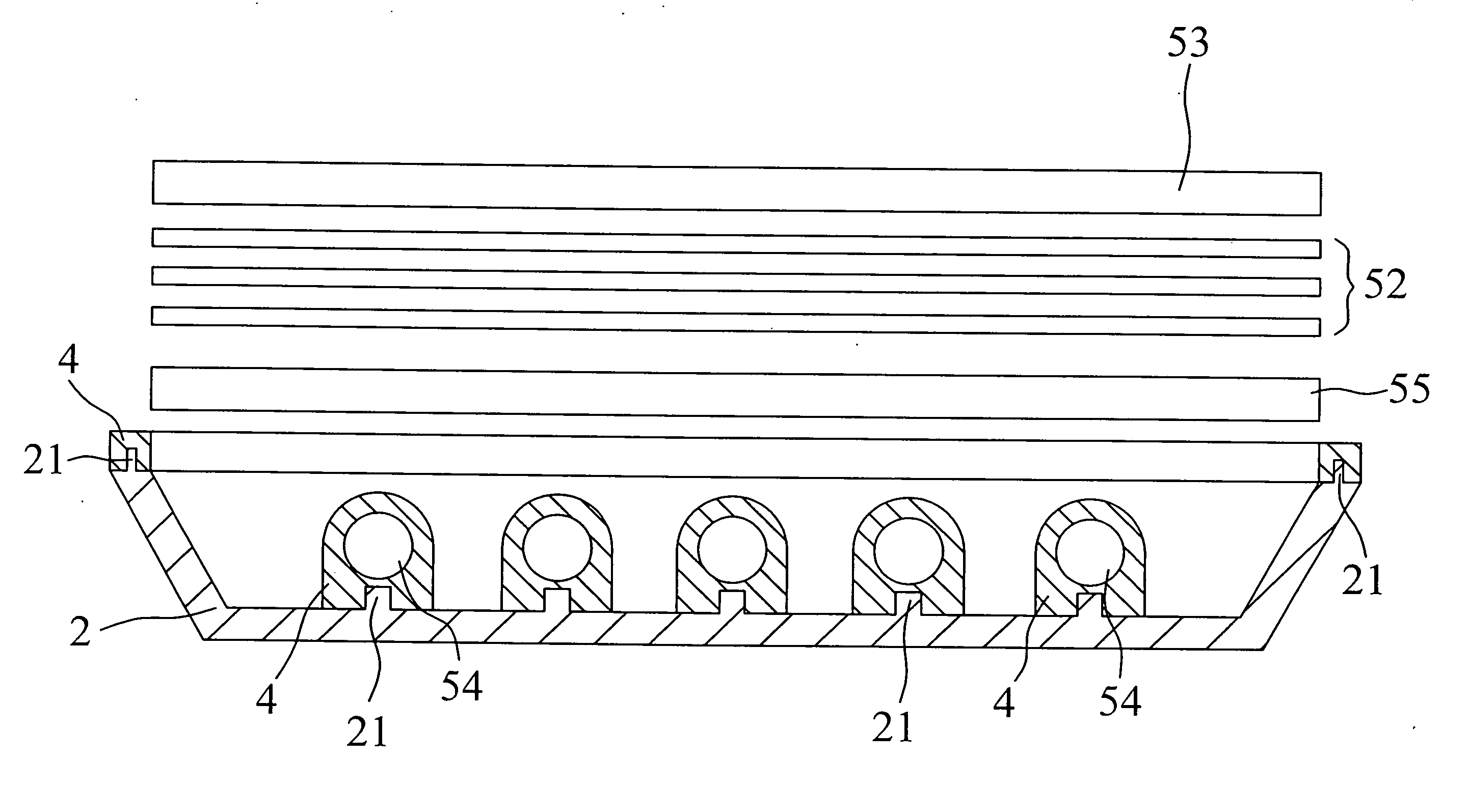
[0023] Wherein, a locating portion 21 is disposed to a first part 2. Before injection the molding material, the locating portion 21 is placed in the molding area 33. When the molding material is injected, cooled and molded in shape, the locating portion 21 extends into the second part and is secured in position. As illustrated in FIGS. 4 and 5, a second part 4 is related to a plastic frame and the first part 2 is related to a metal back plate or a metal reflection layer; both of the plastic frame and the metal back plate or the metal reflection layer are made in an integrated part to facilitate assembling a light guide plate 51, multiple optical films 52, and a liquid crystal...


PUM

PropertyMeasurementUnit
shapeaaaaaaaaaa
moldingaaaaaaaaaa
molding areaaaaaaaaaaa

Abstract

A locating device and method therefore for a first and a second parts of a backlight module by having, for example, a metal back plate or a metal reflection layer and a plastic frame secured to each other and made an integrated party without relying upon any other assembly part, e.g., a screw, or an assembly structure, e.g., an opening and a locking hook, thus to shorten assembly process and to improve assembly strength between the metal back plate or the metal reflection layer and the plastic frame.

Description

BACKGROUND OF THE INVENTION [0001] (a) Field of the Invention [0002] The present invention is related to a backlight module locating device and a method thereof, and more particularly, to a locating installation between a first part and a second part in a backlight module without depending on any other assembly parts or structure to make both of the first and the second parts becoming an integrated part. [0003] (b) Description of the Prior Art [0004] As the fabricating technology for thin film transistor (TFT) rapidly advances, liquid crystal display (LCD) for providing advantages of light and thin, power saving, and radiation free has been massively applied in electronic products including PDA, Notebook, digital camera, camcorder, and mobile phone. Continuous upgrading of LCD quality and price cut of LCD due to ambitious inputs into R&D and up-scaling production facilities further promote fast expansion in LCD-applied field. [0005] Generally, an LCD is not a light emitting display ...

Claims


Application Information

Patent Timeline
Patent Type & Authority Applications(United States)
IPC IPC(8): F21V17/00
CPCB29C45/14336G02F1/133608G02F1/1336B29C45/16
Inventor CHEN, CHIN-HUICHENG, KUO FENG
Owner K-BRIDGE ELECTRONICS CO LTD
Why Eureka
Try Eureka