Fan for mounting on a wall member of a control cabinet

a technology for controlling cabinets and fans, applied in electrical equipment, substation/switching arrangement cooling/ventilation, cooling/ventilation/ventilation, etc., can solve problems such as congestion of air, eddy formation, and inability to connect with a flat wall

Inactive Publication Date: 2001-11-13
RITTALWERK RUDOLF LOH GMBH & CO KG
View PDF10 Cites 31 Cited by
  • Summary
  • Abstract
  • Description
  • Claims
  • Application Information

AI Technical Summary

Benefits of technology

With this design of the fan it is possible to connect the fan unit with the inlet fastening plane of the intermediate housing using one or the other fastening flange, so that the air flow between the air conduit of the wall element and the fan unit is no longer directed vertically on the outer wall leaf, but has a movement component which enhances flow-through and which can be affected and changed depending on the circumstances by a different attachment of the intermediate housing to the wall element.

Problems solved by technology

For reasons of space this is not practical in connection with a flat wall element of a switchgear cabinet, because the fan unit must be attached at different locations of the wall element, depending on the way the switchgear cabinet is equipped.
The wall element made of an outer leaf and an inner leaf forms a very flat air conduit which leads to congestion of the air, since the air flow which is aspirated and fed into the air conduit impacts on the outer wall element, which results in eddy formation.
Moreover, the aspirating direction of the air flow cannot be optimally matched to the existing circumstances if fan units, which are customary in commerce, are to be used.

Method used


Image

  • Fan for mounting on a wall member of a control cabinet
  • Fan for mounting on a wall member of a control cabinet
  • Fan for mounting on a wall member of a control cabinet

Examples


Embodiment Construction

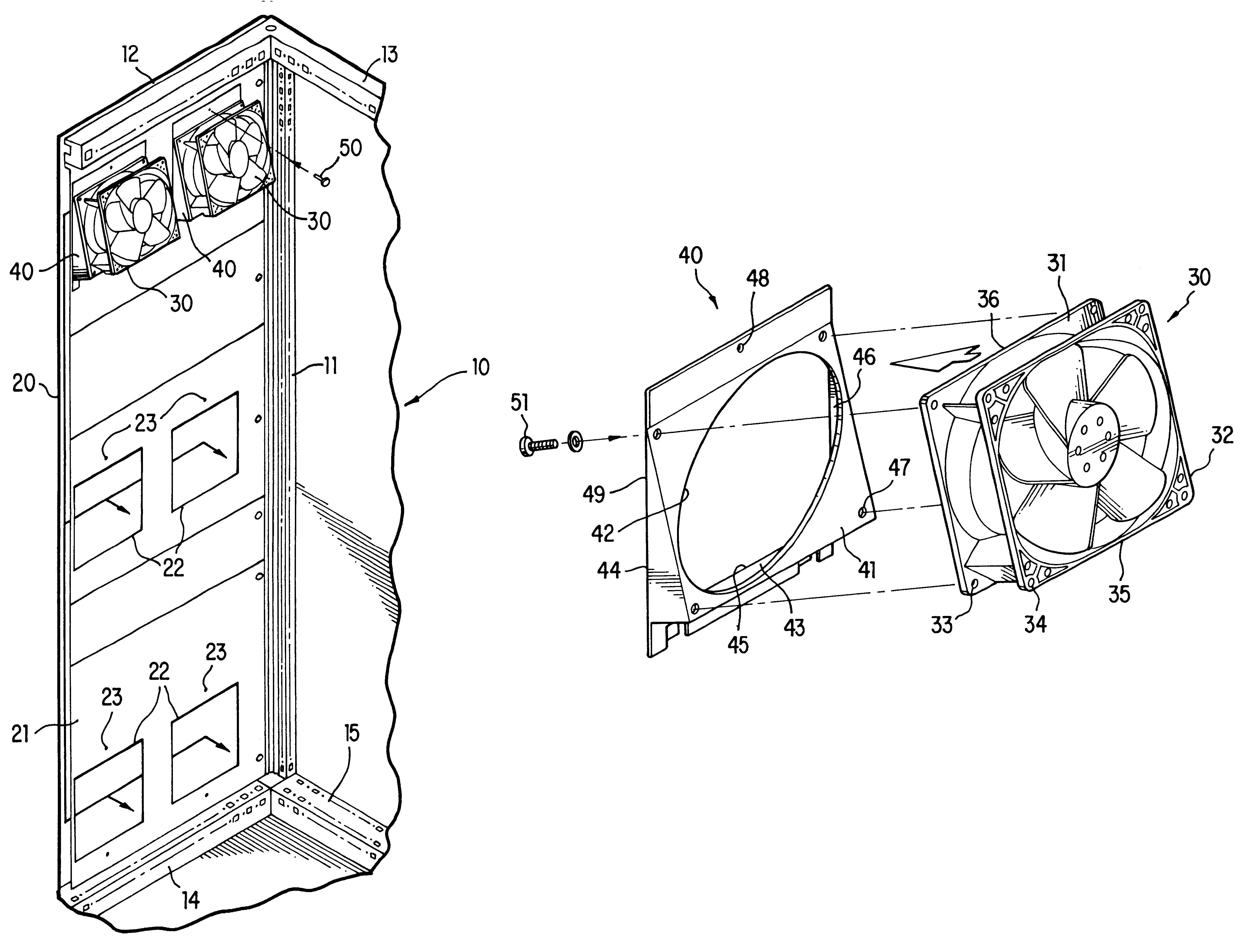
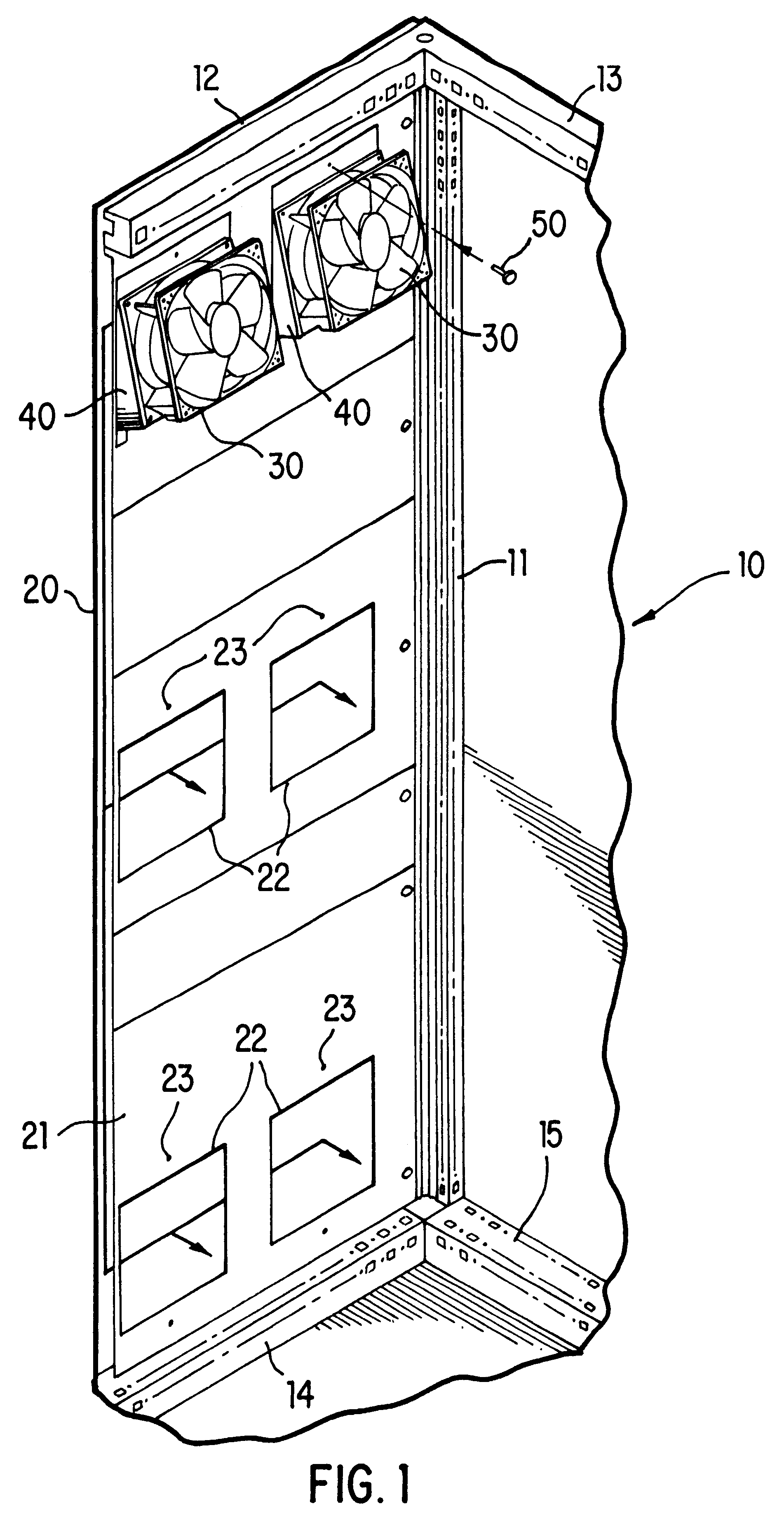
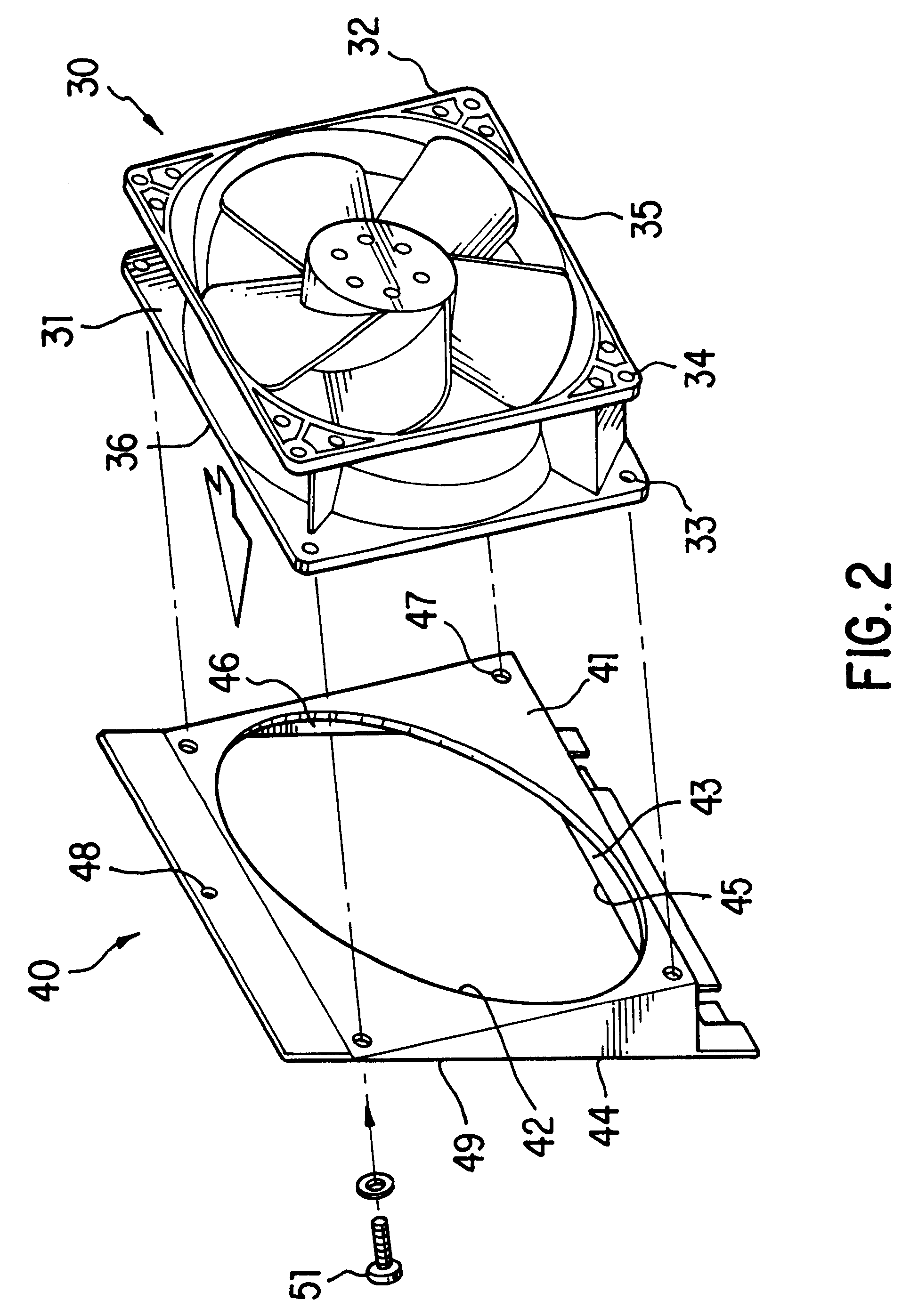
The partial view in accordance with FIG. 1 shows a vertical frame leg 11 of a rack 10 of a switchgear cabinet, on which the horizontal frame legs 12 and 13 are attached at the top, and the horizontal frame legs 14 and 15 are attached at the bottom. One side of the rack 10 is closed by a double-walled wall comprising an inner wall element 21 and an outer wall element 20. The inner wall element 21 has square openings 22 which are connected with each other via the space between the two wall elements 20 and 21. In the exemplary embodiment, the openings 22 are cut in pairs in the upper, central and lower areas of the wall element 21. The space between the two wall elements 20 and 21 can also be divided into air conduits, which vertically connect the openings with each other. In this embodiment the double-walled wall is used as a heat exchanger, when the aspirated warm air from the switchgear cabinet contacts the outer wall element cooled by the outside air, so that the air can return coo...


PUM


Abstract

A fan with an input mounting plane and an output mounting plane. The fan is adapted to be mounted on a control cabinet wall member with an aeration passage. This invention produces an air flow which is as dust-free and turbulence-free as possible. For this purpose, the input mounting plane and the output mounting plane form an acute angle.

Description

1. Field of the InventionThis invention relates to a fan with an inlet mounting plane and an outlet mounting plane for installation on a wall element, which has a ventilation opening, of a switchgear cabinet, wherein a fan unit has fastening flanges on the inlet and outlet sides which are identical and are oriented parallel with respect to each other and is assembled from the fan unit and an additional housing.2. Description of Related ArtFan units of this type are known in diverse embodiments, wherein they can be directly connected with the wall element by one or the other fastening flange. Such fan units are conventional and can be provided in various sizes and use requirements. As a rule, the air flow is oriented the same in the area of the inlet and outlet fastening planes, as well as vertically with respect to these planes, as can be determined from PCT International Application WO 96 / 41511.As is known from Patent Abstracts of Japan, volume 18, No. 480 (E1603), Sep. 8, 1994, an...

Claims


Application Information

Patent Timeline
IPC IPC(8): H02B1/00H02B1/56H05K7/20
CPCH02B1/565H05K7/20172
Inventor PAWLOWSKI, ADAM
Owner RITTALWERK RUDOLF LOH GMBH & CO KG
Why Eureka
Try Eureka