Suction device with means for removing a replaceable tip

a technology of suction device and replaceable tip, which is applied in the direction of burettes/pipettes, instruments, glassware laboratories, etc., can solve the problem of increasing the risk of contamination again

Inactive Publication Date: 2001-12-04
SARTORIUS BIOHIT LIQUID HANDLING
View PDF6 Cites 19 Cited by
  • Summary
  • Abstract
  • Description
  • Claims
  • Application Information

AI Technical Summary

Problems solved by technology

In these cases the tips have to be removed manually,

Method used


Image

  • Suction device with means for removing a replaceable tip
  • Suction device with means for removing a replaceable tip
  • Suction device with means for removing a replaceable tip

Examples


Embodiment Construction

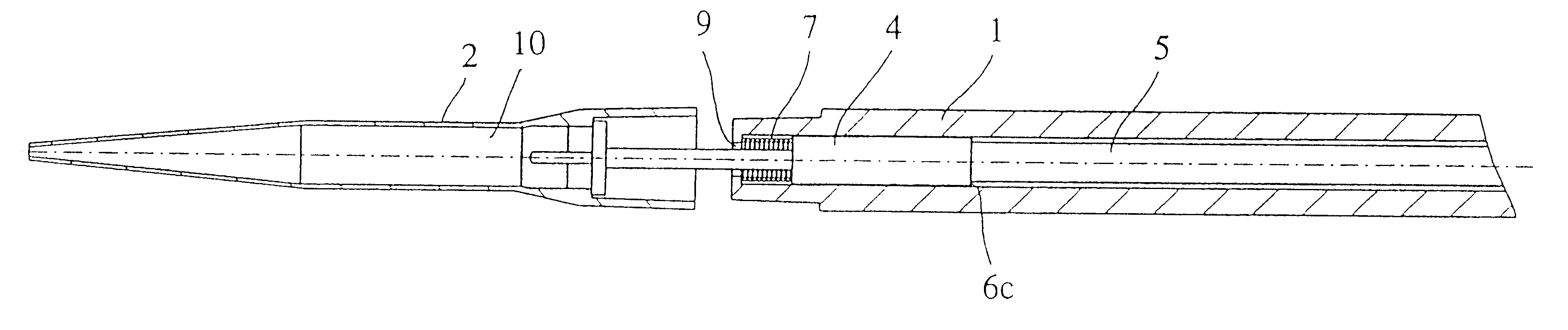
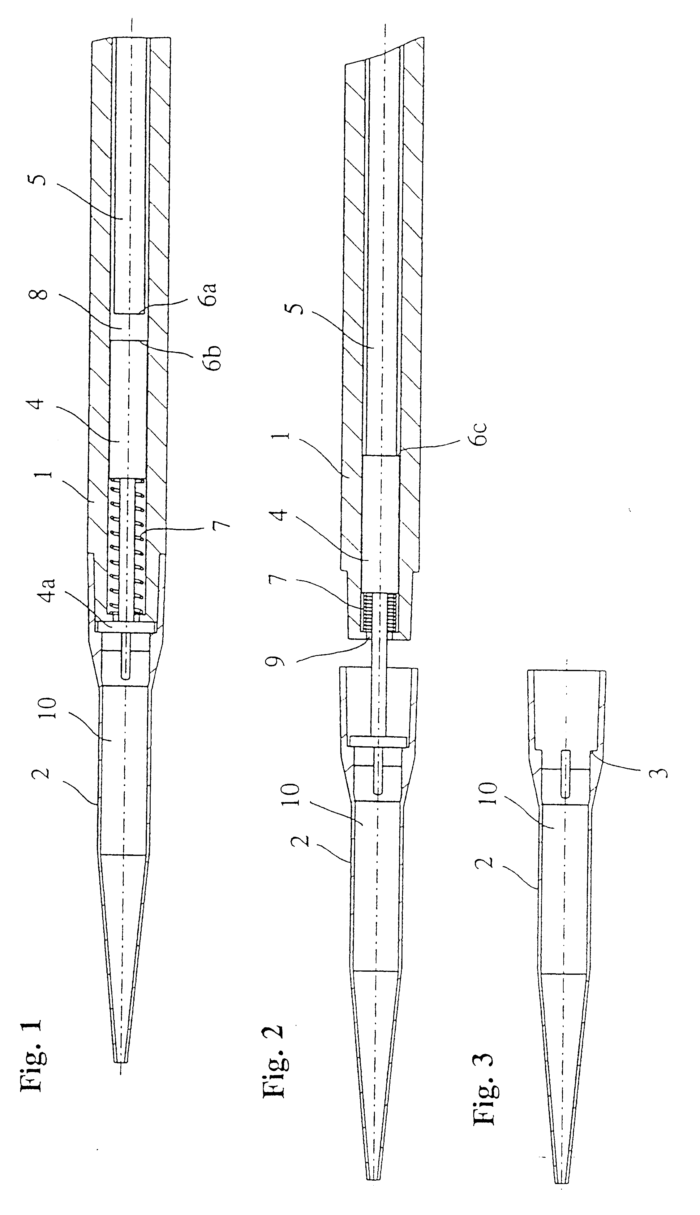
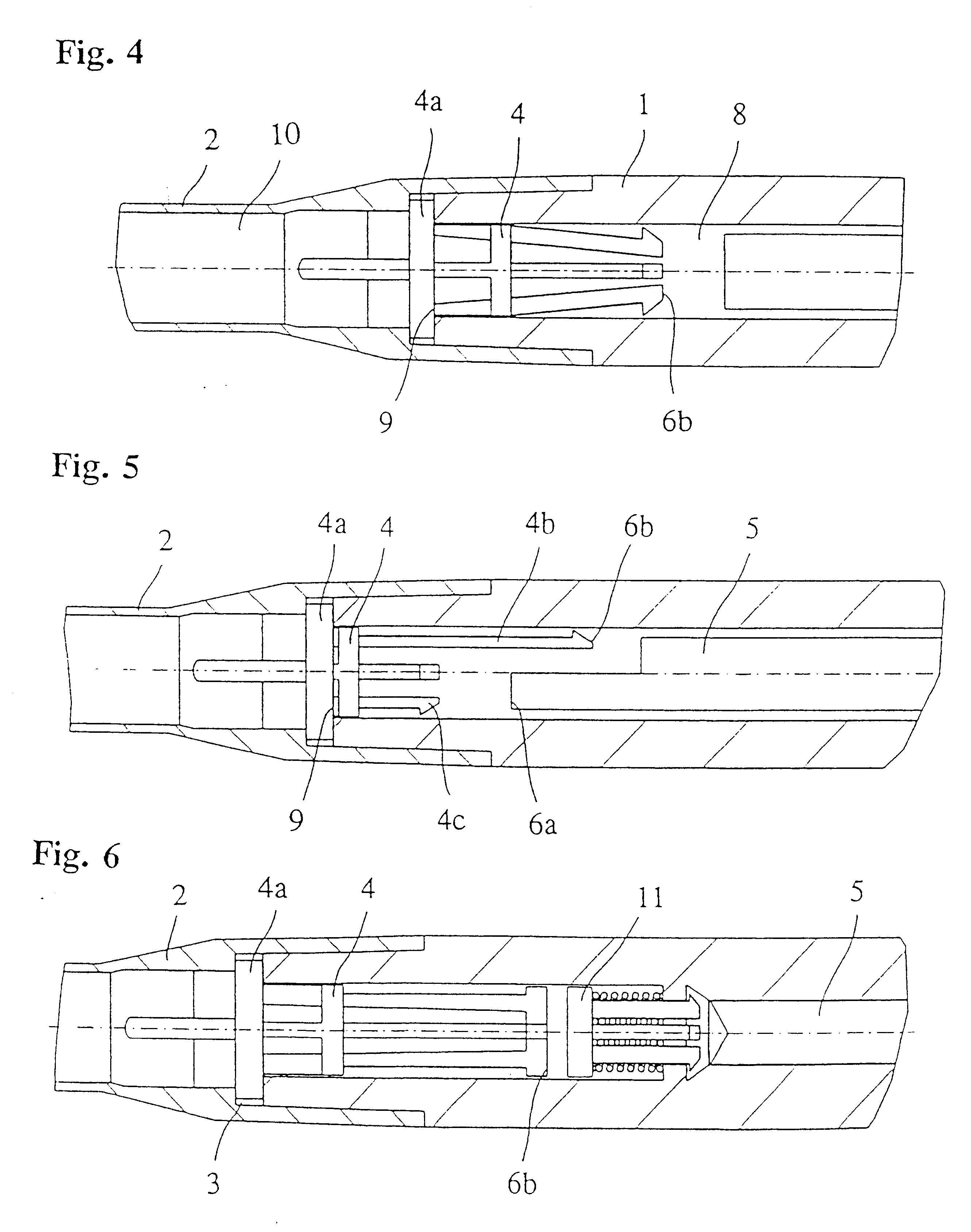
In the FIGS. 1-6 the same reference numbers are used for parts corresponding to each other. In FIG. 1 the end part of the suction device is referenced with number 1, the replaceable tip adapted onto the end part with number 2, its sample space with number 10 and the removal means with number 4. In the cylindrical air space 8 of the end part the piston 5 moves slidingly for changing the volume of the cylindrical space 8. In the illustrated embodiment the position 6a of the piston 5 is the home position of the piston and the position 6b is the home position of the removal means 4. The spring 7, which is mounted in the cylindrical space 8 between the distal end of the end part 1 of the suction device and the removal means, holds the removal means 4 in its home position 6b. In its home position 6a the piston 5 is not in contact with the removal means 4 in its home position 6b. When the replaceable tip 2 is to be detached, the piston 5 is brought to move past its home position 6a, whereb...


PUM


Abstract

A method for removing a replaceable tip used with a suction device for dispensing a liquid removes the tip by bringing a removal device, arranged in an air space formed jointly by a sample space of a replaceable tip and a cylindrical space of an end part of a suction device, movable between its two extreme positions, namely an inner home position and an outer removal position, into cooperation with an inside surface of the replaceable tip mounted on the end part whereby the movement of the removal device into its removal position causes the replaceable tip to be detached from the end part. A suction device is provided for using the method.

Description

The object of this invention is a method for removing a replaceable tip for use in a suction device for dispensing, transferring, diluting, titrating, or mixing a liquid, or for a combination of all or some of these operations.The object of this invention is also a suction device for dispensing, transferring, diluting, titrating or mixing a liquid, or for a combination of all or some of these operations, which suction device has an end part enclosing a cylindrical space having a reciprocating piston for changing the volume of the cylindrical space, the end part being provided with an aperture in the extremity thereof intended for receiving a replaceable tip, in order to form a gas passage between the sample space of the said replaceable tip and the cylindrical space, and which has means for removing the tip.DESCRIPTION OF THE BACKGROUND ARTSince the 1970s suction devices have been in use, in which the replaceable tip has been released and removed from the body with mechanical means ...

Claims


Application Information

Patent Timeline
IPC IPC(8): B01L3/02G01N35/10
CPCB01L3/0279
Inventor SUOVANIEMI, OSMOEKHOLM, PERTTI
Owner SARTORIUS BIOHIT LIQUID HANDLING
Why Eureka
Try Eureka