Method and apparatus for DC offset correction

a dc offset and offset correction technology, applied in the direction of dc level restoring means or bias distort correction, phase-modulated carrier system, pulse technique, etc., can solve the problem of more difficulties in dc offset correction, insufficient baseband filter function, and introduction of tremendous distortion in fm demodulation

Inactive Publication Date: 2001-12-04
APPLE INC
View PDF12 Cites 140 Cited by
  • Summary
  • Abstract
  • Description
  • Claims
  • Application Information

AI Technical Summary

Problems solved by technology

DC offset correction is one of the most critical problems in the design of direct conversion receivers. FIG. 1 is a block diagram of a conventional DC offset correction loop 100 such as would be used in the baseband path of a direct conversion receiver, cell phone, or other communication device.
Mismatches between devices in a direct conversion radio system create DC offset in the down mixer and baseband filter.
This offset can introduce tremendous distortion in the FM demodulation and even m

Method used


Image

  • Method and apparatus for DC offset correction
  • Method and apparatus for DC offset correction
  • Method and apparatus for DC offset correction

Examples


Embodiment Construction

While the specification concludes with claims defining the features of the invention that are regarded as novel, it is believed that the invention will be better understood from a consideration of the following description in conjunction with the drawing figures.

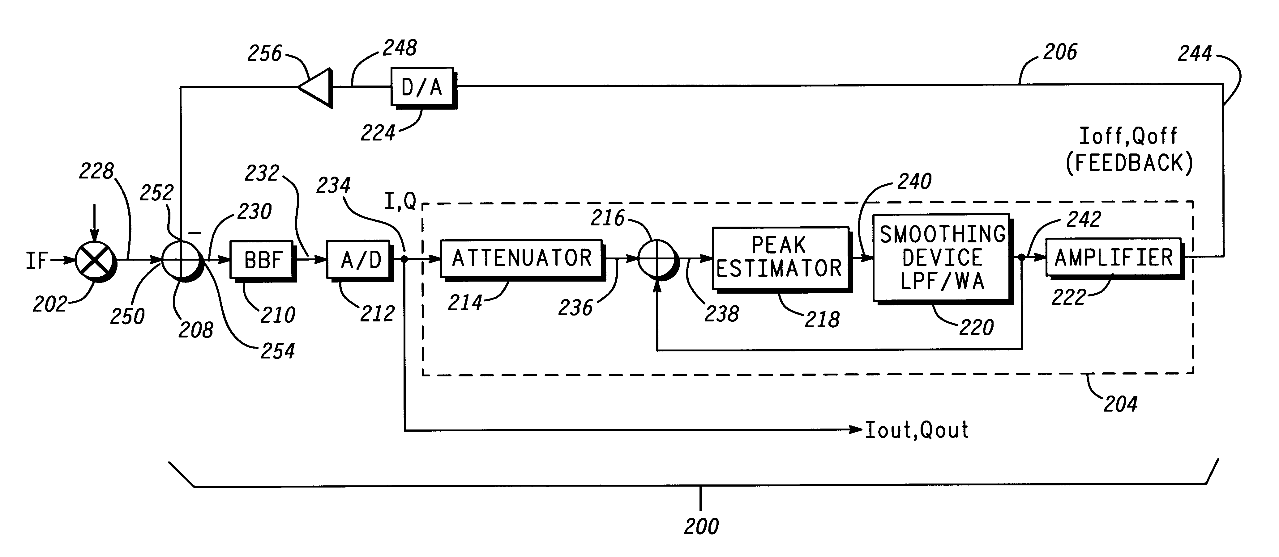
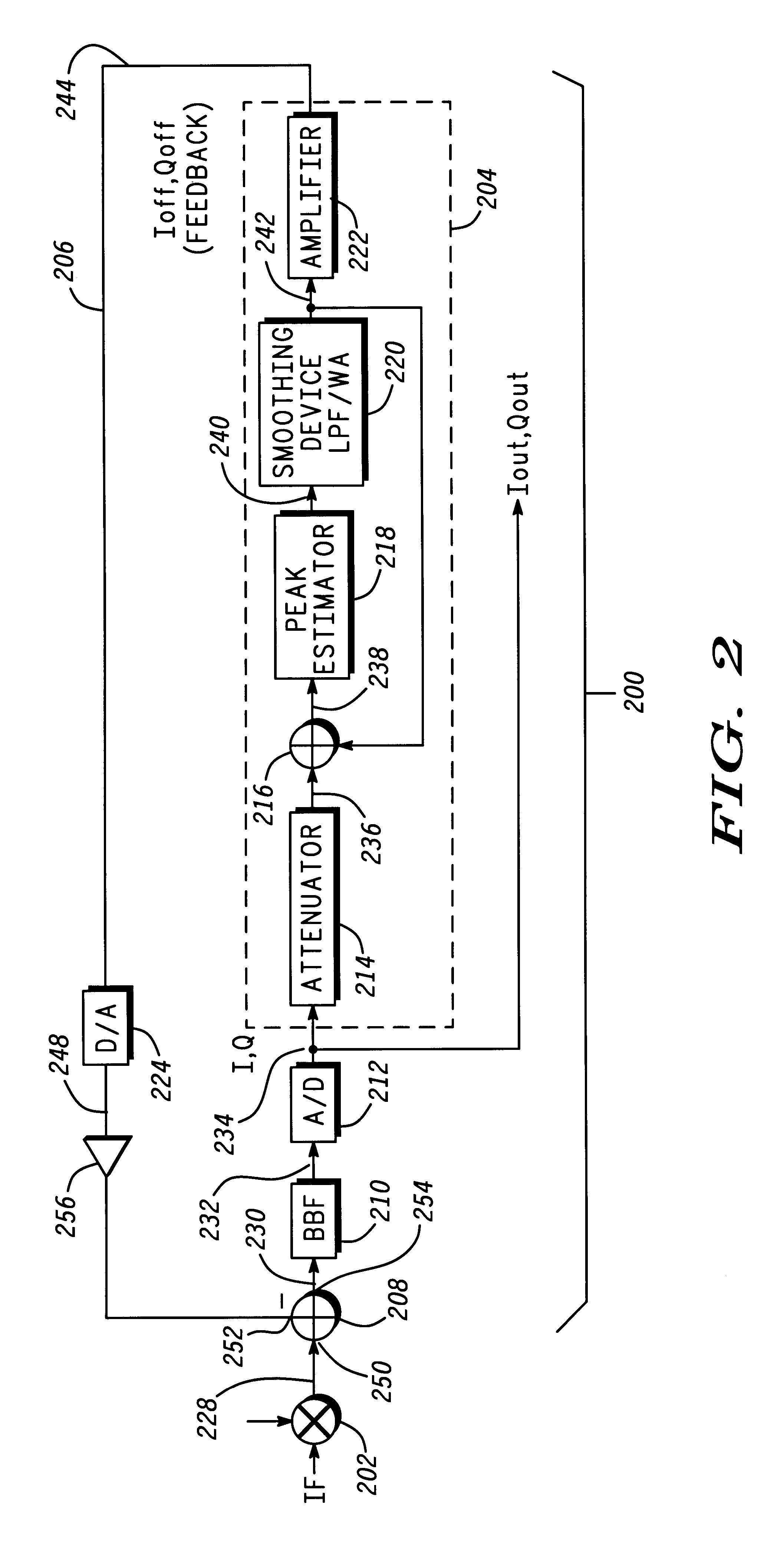
Briefly, in accordance with the present invention a DC offset correction loop incorporates a peak estimator into the loop for receiving a digital signal (I / Q signal). The peak estimator determines peaks associated with the I / Q signal and averages the peaks in order to estimate the DC offset. A summer then sums the DC offset with the I / Q signal to produce a corrected output for the loop. The peak estimator is shown and described herein as part of two DC correction loop embodiments. Also, in accordance with the present invention, corresponding peak estimation techniques provided herein offer a method of receiving a digital signal, estimating the peaks of the digital signal, averaging the peaks of the digital signal to estimate...


PUM


Abstract

A DC offset correction loop (200, 300) utilizes a peak estimator (218, 322) to determine peaks associated with a digital signal (238, 338). The peak estimator (218, 322) averages the peaks in order to estimate the DC offset. A summer (216, 326) sums the DC offset (242, 350) with the digital signal to produce a corrected output.

Description

TECHNICAL FIELDThis invention relates to techniques and apparatus for minimizing DC offsets in electronic circuits.BACKGROUNDTraditional superheterodyne receivers translate incoming radio signals to one or more intermediate frequencies where successive stages of amplification, baseband filtering and gain control are applied. Direct conversion architecture uses a single mixer with a single oscillator tuned to the desired signal frequency, converting a signal directly to baseband-the zero intermediate frequency "ZIF" signal. Direct conversion receivers have been gaining in popularity in the electronic communications environment.DC offset correction is one of the most critical problems in the design of direct conversion receivers. FIG. 1 is a block diagram of a conventional DC offset correction loop 100 such as would be used in the baseband path of a direct conversion receiver, cell phone, or other communication device. Correction loop 100 is shown coupled to a mixer 102 and generally ...

Claims


Application Information

Patent Timeline
IPC IPC(8): H04L25/06
CPCH04L25/063
Inventor TRAYLOR, KEVIN B.FANG, JING
Owner APPLE INC
Why Eureka
Try Eureka