
Mechanism for constant balance with method for manufacture of variable pitch screw

a constant balance, variable-pitch technology, applied in the direction of mechanical equipment, door/window protective devices, wing accessories, etc., can solve the problems of system overbalance, excessive operation force, and over-driven mechanism

Inactive Publication Date: 2001-12-18
WEINREICH STEVE
View PDF25 Cites 23 Cited by
  • Summary
  • Abstract
  • Description
  • Claims
  • Application Information

AI Technical Summary

Benefits of technology

Achieving constant balance allows the use of various actuators which were not previously practical. The mechanism can be overdriven to allow short throw levers, cords, or chains that, in a non-balanced system would require excessive force to operate. The bottom bar of a shade or blind can be directly pulled down or lifted by hand and will remain where it is released. The need for latches, clutches, or cleats is eliminated. Motorized embodiments can take advantage of the reduced operating force to use smaller and quieter motors. Motors for systems comprising the invention may be battery operated, particularly using solar cells (which collect light from the window being shaded) to recharge the batteries.

Problems solved by technology

The mechanism can be overdriven to allow short throw levers, cords, or chains that, in a non-balanced system would require excessive force to operate.
It is easier to pull down than to lift so the system may be overbalanced to favor lifting.

Method used


Image

  • Mechanism for constant balance with method for manufacture of variable pitch screw
  • Mechanism for constant balance with method for manufacture of variable pitch screw
  • Mechanism for constant balance with method for manufacture of variable pitch screw

Examples


Embodiment Construction

TYPICAL SHADE ROLLER

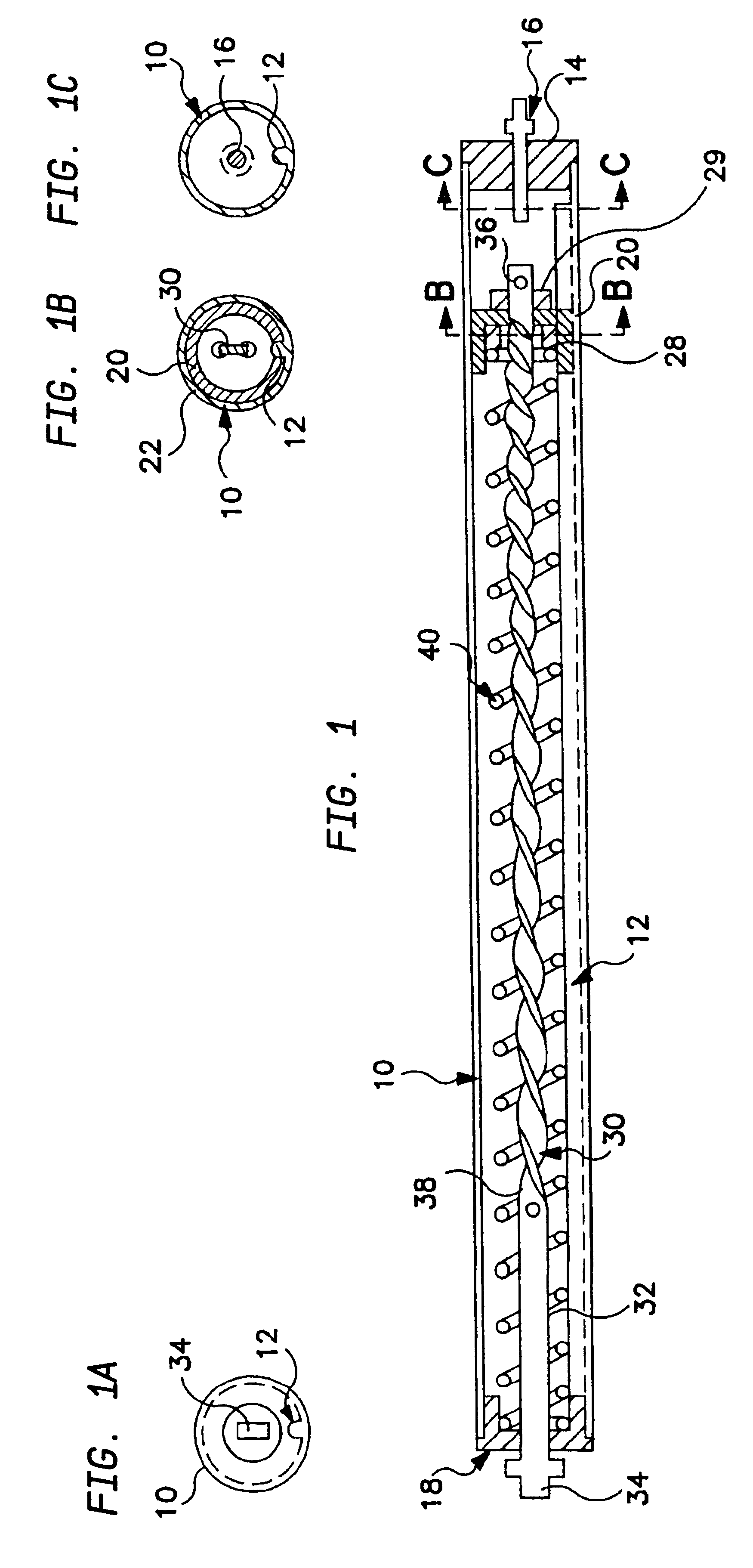
Referring to the drawings, FIG. 1 shows a roller [10] which is a hollow tube, preferably of metal such as aluminum, having an internal longitudinal protrusion [12]. The internal longitudinal protrusion may be formed to provide a slot on the external surface of the roller such as is known in the art to receive the top edge of the roller shade (not shown). In one end of the roller [10] is mounted an end cap [14] holding at its center a round pin [16] which rotatably supports that end of the roller [10] in an end bracket (not shown) such as is known in the art. In the other end of the roller [10] is mounted an end cap [18] having a round hole to accommodate one end of a twisted bar [30].

A cup [20], preferably of plastic such as teflon is slip fitted into the roller [10]. The outside cylindrical wall of the cup [20] is slotted to fit over the internal longitudinal projection [12] so that the cup may translate along the interior of the roller [10], but not rotate rela...


PUM


Abstract

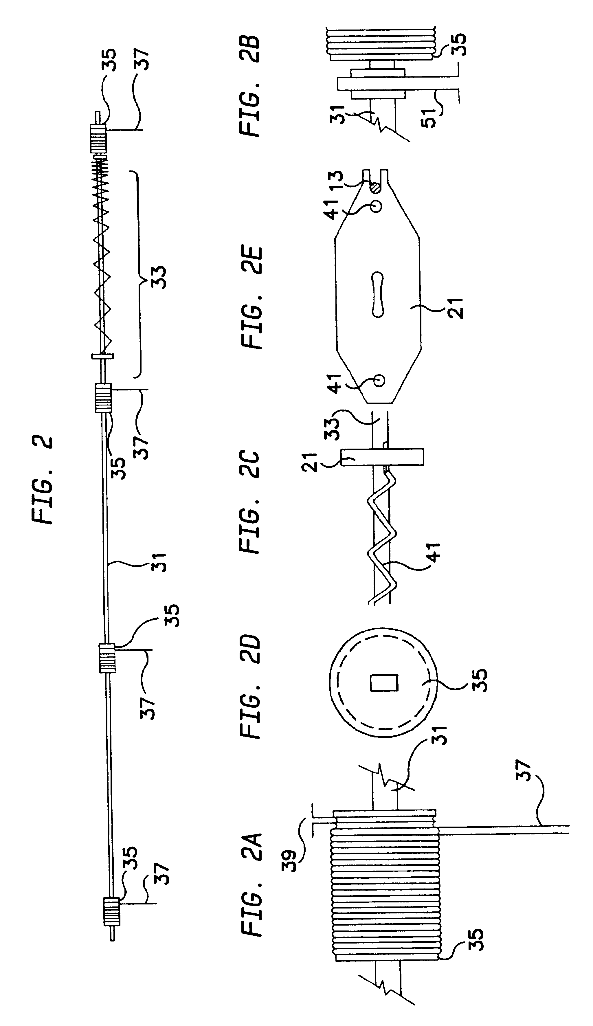
A variable pitch screw is manufactured by twisting a prepared blank to the desired shape. The blank varies along its length such that it naturally twists to the desired shape.

Description

Window shades and blinds have been provided with various mechanisms to facilitate lifting. Among the roller shade mechanisms are the common spring loaded shade roller, shade rollers which are operated by chain wheels, inverted shades with rollers at the bottom, and shade rollers with internal motors. Blind mechanisms include the common venetian models and others mostly distinguished by the type of blind rather than the lifting method.Of the above, only the common shade roller provides a means to balance the weight to be lifted and, even so, the shade must be overbalanced for proper operation of the mechanism. Furthermore, there is no arrangement to provide consistency in the balancing force versus the changing load of the shade as it is rolled up. This is apparent to anyone who has ever let go of a window shade without first setting the latching mechanism and has watched the shade abruptly snap upwards.This invention uniquely provides a variable balancing force to track the changing...

Claims


Application Information

Patent Timeline
Patent Type & Authority Patents(United States)
IPC IPC(8): E06B9/62E06B9/56
CPCE05D13/1207E05D13/123E06B9/62E05Y2201/618E05Y2201/696E05Y2201/608E05Y2900/106E05Y2900/00
Inventor WEINREICH, STEVE
Owner WEINREICH STEVE
Learn More