Lifting sling system with spaced, bi-directional loops

Inactive Publication Date: 2001-12-18
GULLEY WILLIAM F
View PDF22 Cites 33 Cited by
  • Summary
  • Abstract
  • Description
  • Claims
  • Application Information

AI Technical Summary

Benefits of technology

In view of the above, it is a feature of the present invention to provide a sling which is relatively simple and inexpensive to manufacture.
Another feature of the present invention is to

Problems solved by technology

However, the known slings do not prevent longitudinal twisting and turning of the sling as the heavy pipes or other objects are suspended in mid-air via a closed lifting loop.
Moreover, known slings do not provide bi-directional loops which serve to distribute s

Method used


Image

  • Lifting sling system with spaced, bi-directional loops
  • Lifting sling system with spaced, bi-directional loops
  • Lifting sling system with spaced, bi-directional loops

Examples


Embodiment Construction

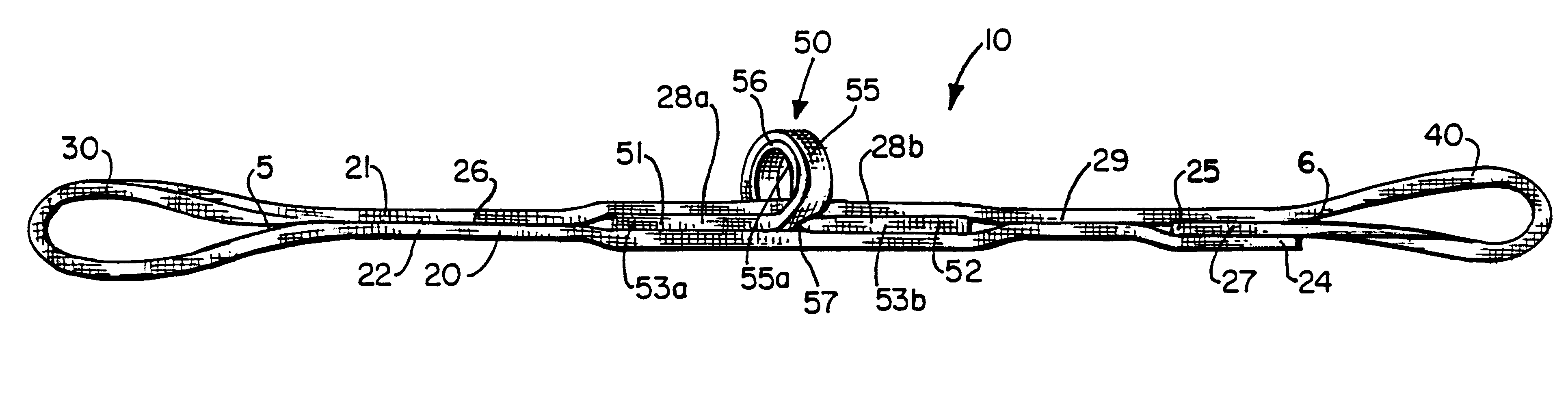
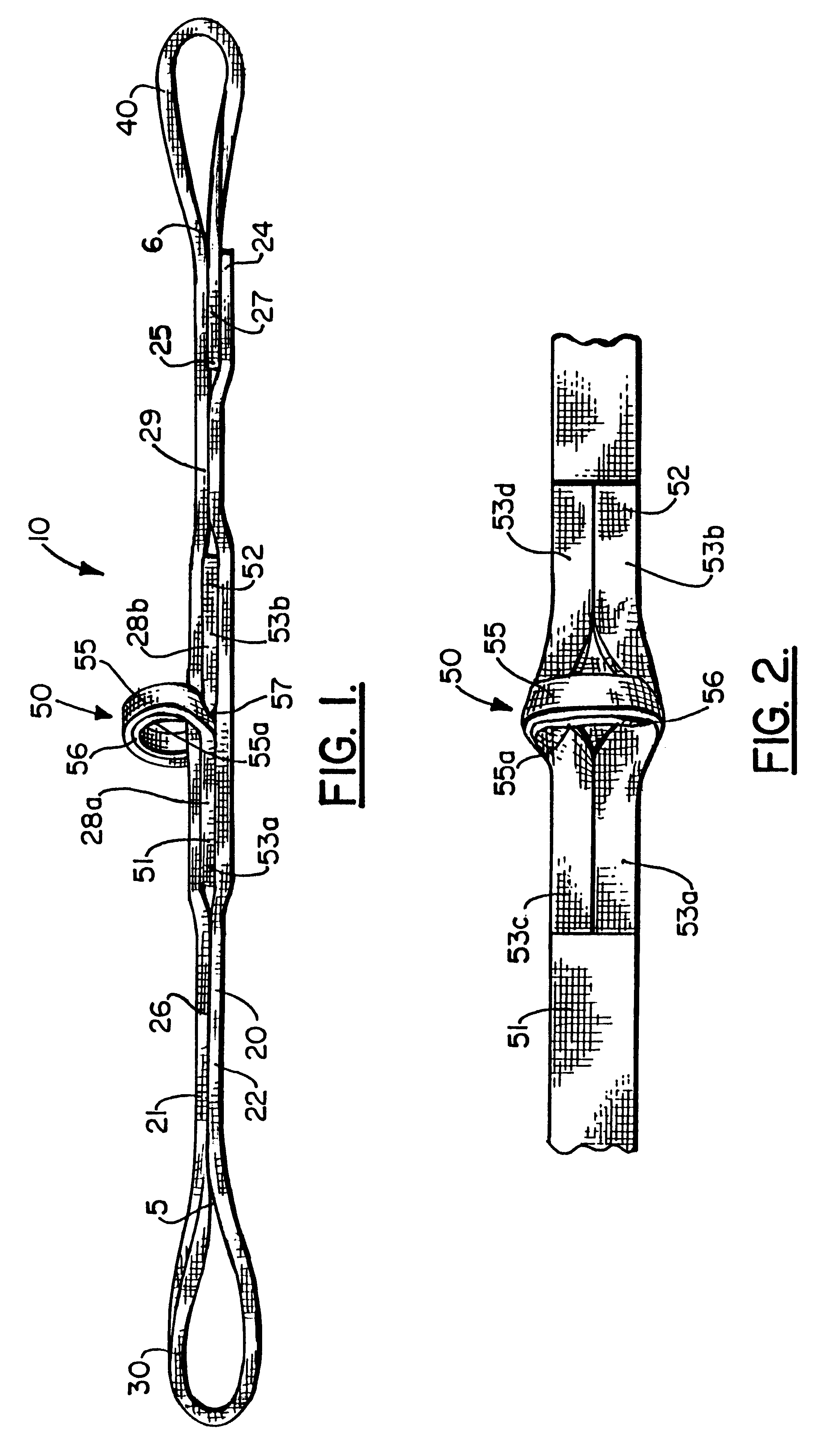
Referring now to the drawings, and in particular to the side view of FIG. 1, the first, exemplary, preferred sling of the present invention is designated generally by the numeral 10. The sling 10 is generally comprised of a two-ply sling strap member 20, a first terminal, eye-loop end 30, a second, terminal eye-loop end 40 and at least one bi-directional loop 50 located intermediate the terminal ends.

The two-ply sling strap member 20 preferably comprises a single, integral, strap piece over-lappingly converging upon itself to form a top or upper strap member 21 and a bottom or lower strap member 22. The two-ply sling strap member 20 comprises, for example, a two (2") inch wide, strap made of flexible material such as, without limitation, woven nylon. The ends of the single strap of the two-ply sling strap member 20 comprise a first strap end 24 and a second strap end 25.

As the single strap over-lappingly converges upon itself, a first eye-loop end 30 is formed and immediately adjace...


PUM


Abstract

A sling (10, 10', FIGS. 1-3) for lifting a heavy work piece (e.g. a pipe section; FIGS. 5, 6), including a single strap made of flexible, in-elastic fabric material over-lappingly converging upon itself to form a top strap member and a bottom strap member to form a two-ply strap member; a first, integral, eye-loop end; a second, integral eye-loop end; at least one, intermediately spaced, bi-directional loop (50, 150a-d) coupled to the two-ply strap member between the first and second, eye-loop ends. Each bi-directional loop serves to distribute suspension stresses in two directions, longitudinally, along the lifting sling when used to complete the closed lifting loop and distribute pulling forces in either of two directions, longitudinally, along the sling when pulled in any or either longitudinal direction. Additionally, since crane time is very expensive to operate, a sling system which can accommodate the lifting of a plurality of heavy pipes or other heavy objects simultaneously is provided (FIGS. 8-7).

Description

The present invention relates to slings for holding, lifting or otherwise manipulating a heavy load or other heavy object, and in particular to slings constructed of fabric (e.g. nylon) strapping material having a plurality of spaced bi-directional loops used in connection with, for example, one or more connecting shackles or other means of fastening, for use with loads of various sizes. An exemplary pipe load with which the invention is used typically weighs, for example, hundreds of pounds or greater. Furthermore, the sling of the present is capable of suspending therefrom simultaneously a plurality of heavy pipe loads or other heavy objects. The invention also relates to sling use methodology and methods of manufacturing slings.Slings for lifting and carrying heavy pipes or other like heavy objects are known. However, the known slings do not prevent longitudinal twisting and turning of the sling as the heavy pipes or other objects are suspended in mid-air via a closed lifting loo...

Claims


Application Information

Patent Timeline
IPC IPC(8): B66C1/18B66C1/12
CPCB66C1/18D07B1/18
Inventor GULLEY, WILLIAM F.
Owner GULLEY WILLIAM F
Why Eureka
Try Eureka