Brushless motor for vehicle air conditioner

a brushless motor and air conditioner technology, applied in the direction of windings, magnetic circuit shapes/forms/construction, transportation and packaging, etc., can solve the problem of limiting the operation of motors

Inactive Publication Date: 2001-12-25
ASMO CO LTD
View PDF11 Cites 86 Cited by
  • Summary
  • Abstract
  • Description
  • Claims
  • Application Information

AI Technical Summary

Benefits of technology

In view of the foregoing problems, it is an object of the present invention to provide...

Problems solved by technology

As a result, failure ...

Method used


Image

  • Brushless motor for vehicle air conditioner
  • Brushless motor for vehicle air conditioner
  • Brushless motor for vehicle air conditioner

Examples


first embodiment

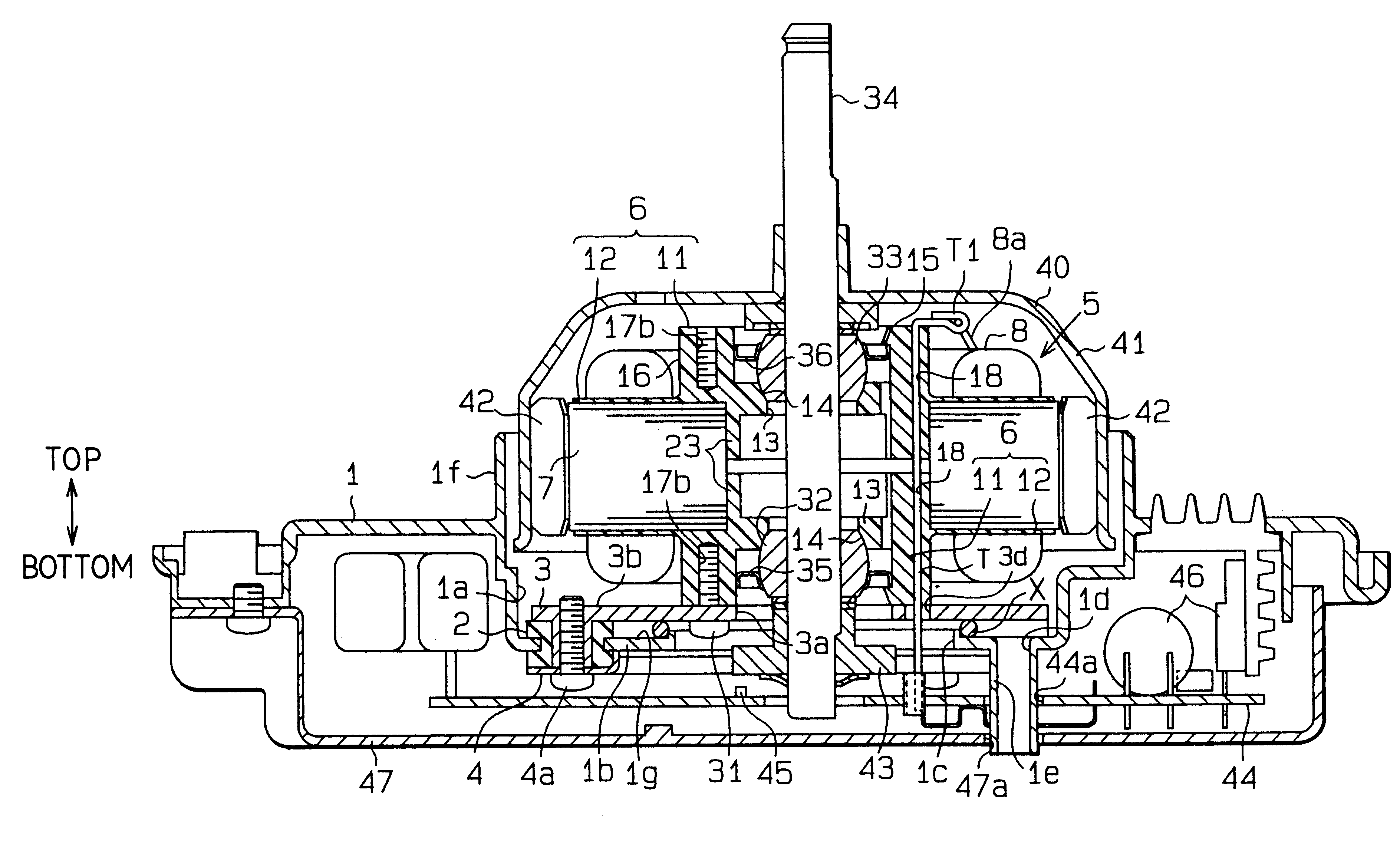
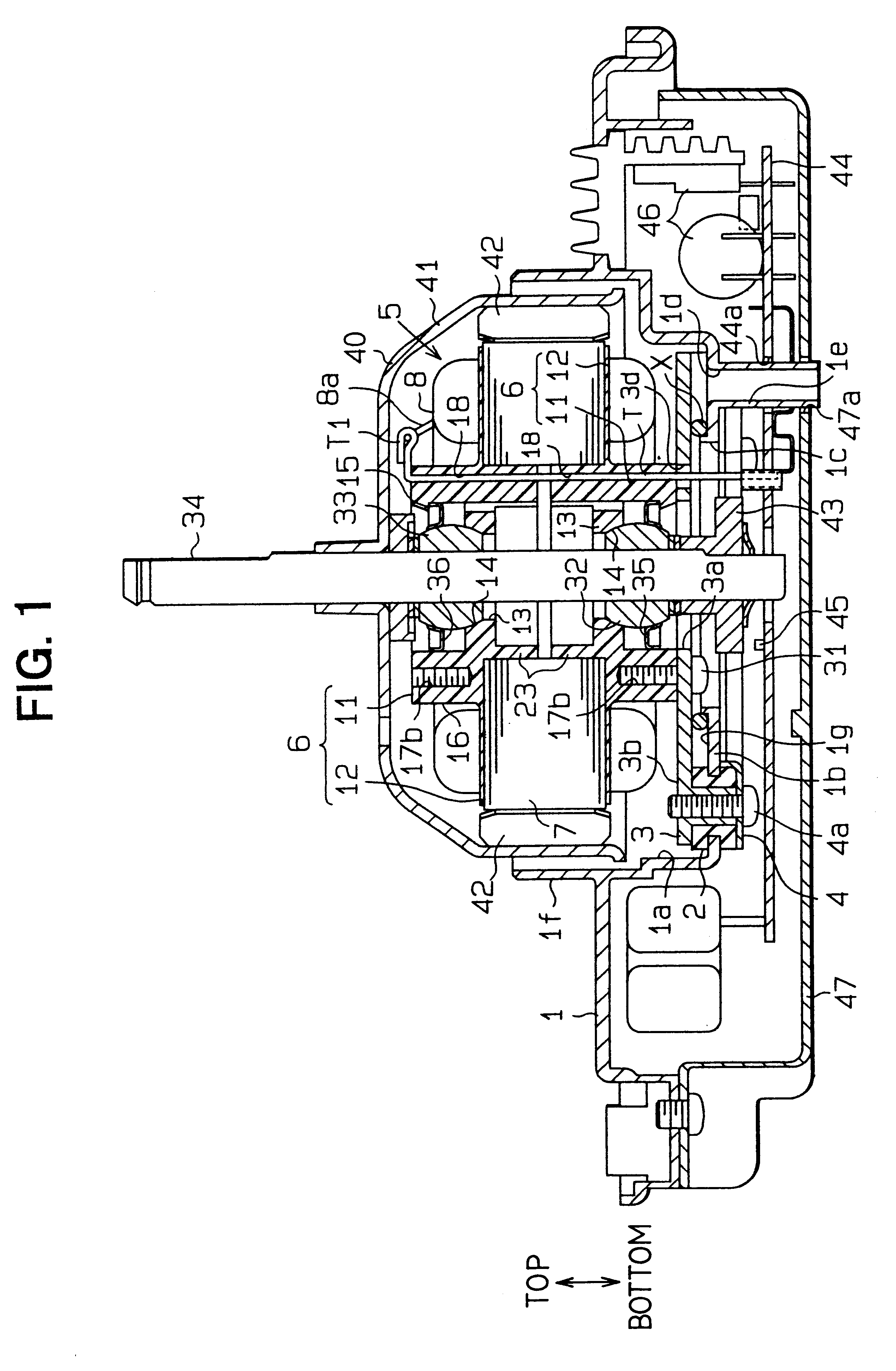
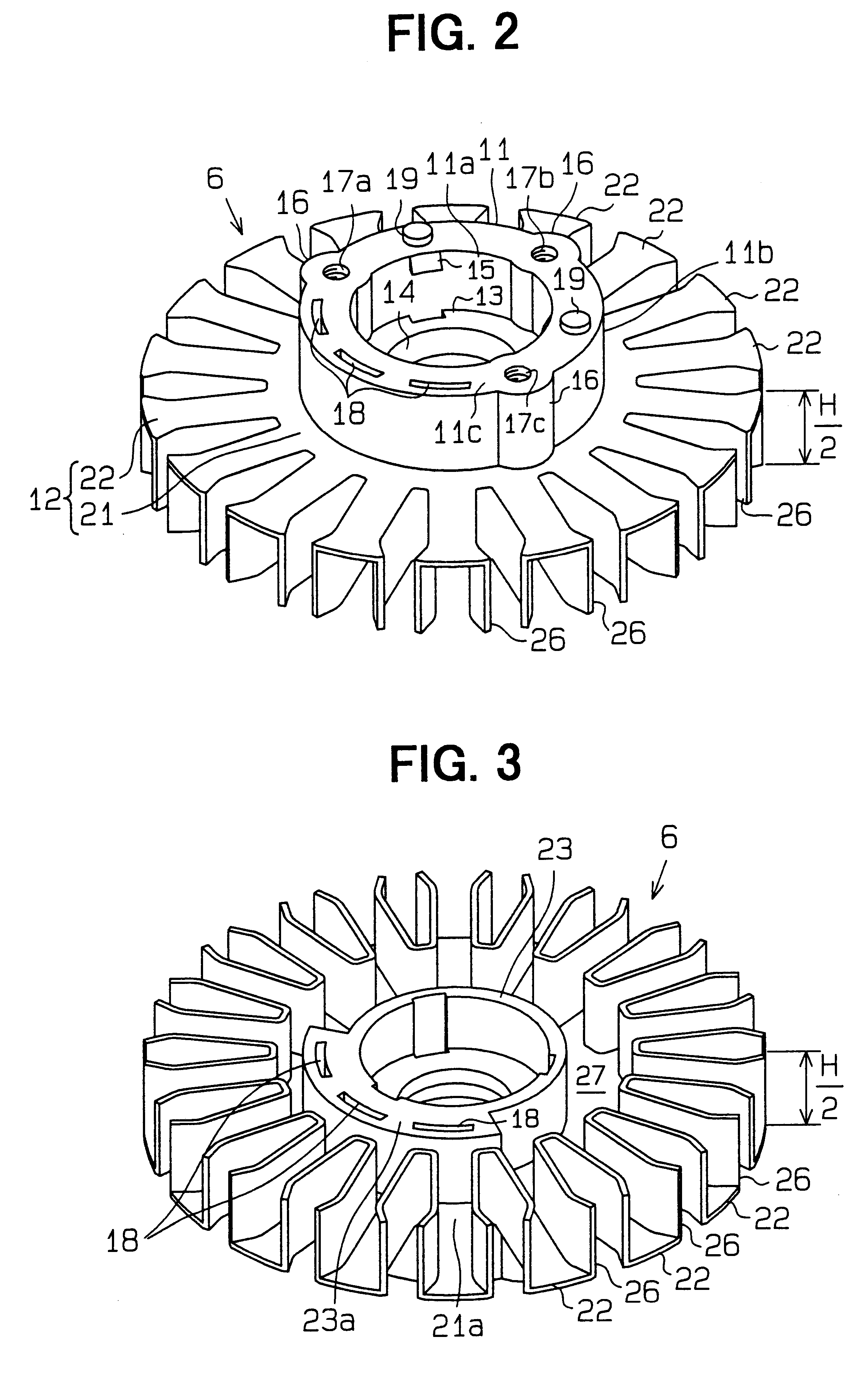
A first preferred embodiment of the present invention will be described with reference to FIGS. 1-7.

As shown in FIG. 1, a brushless motor for a vehicle air conditioner has a motor holder 1. The motor holder 1 has a circular accommodation portion 1a formed to be recessed at a center thereof. A bottom 1b of the accommodation portion 1a has a through hole 1c at a center thereof and a drain opening 1d. A drain pipe 1e is connected to the drain opening 1d and extends downwardly to a predetermined position. The motor holder 1 also has a waterproof wall 1f which extends upwardly from a periphery of an opening of the accommodation portion 1a.

A substantially disc-shaped mount plate 3 is mounted to an upper surface of the bottom 1b through plural rubber mounting members 2. In FIG. 1, only one of the mounting members 2 is shown. The mount plate 3 is fastened to a back plate 4 disposed below the motor holder 1 through a screw 4a. The mount plate 3 has a center hole 3a having a diameter smaller ...

second embodiment

A second preferred embodiment of the present invention will be described with reference to FIGS. 8 and 9. In this and following embodiments, components which are substantially the same as those in previous embodiments are assigned the same reference numerals. In the second embodiment, the upper and lower center pieces 6 and the core 7 in the first embodiment are respectively replaced with a center piece 51 and a core 55.

As shown in FIG. 8, the center piece 51 is made of metal and is formed by pressing to have a cylindrical portion 52 and a flange portion 53 extending from a lower end of the cylindrical portion 52 outwardly in a radial direction of the cylindrical portion 52. The flange portion 53 is fastened to the bottom 1b of the accommodation portion 1a through the mounting members 2. In the second embodiment, the drain opening 1d is not formed in the bottom 1b. Upper and lower bearings 54 are attached to an inner circumferential wall of the cylindrical portion 52 so that the rot...

third embodiment

A third preferred embodiment of the present invention will be described with reference to FIGS. 10 and 11. In the third embodiment, the upper and lower center pieces 6 and the core 7 in the first embodiment are respectively replaced with a center piece 71 and a core 75.

As shown in FIG. 10, the center piece 71 is made of metal and is formed by pressing to have a cylindrical portion 72 and a flange portion 73 extending from a lower end of the cylindrical portion 72 outwardly in a radial direction of the cylindrical portion 72. The flange portion 73 is mounted to the bottom 1b of the accommodation portion 1a through the mounting members 2. In the third embodiment, the bottom 1b does not have the drain opening 1d. Upper and lower bearings 74 are attached to an inner circumferential wall of the cylindrical portion 72 so that the rotation shaft 34 is rotatably held by the bearings 74. The cylindrical portion 72 is press-fit into an opening of the core 75.

The core 75 is formed by laminatin...


PUM


Abstract

A brushless motor for a vehicle air conditioner has a motor holder having an accommodation portion, a stator having a center piece fastened to a bottom of the accommodation portion and a core on which a winding is wound, and an exciting circuit disposed below the bottom to supply an exciting current to the winding. A terminal of the exciting circuit is upwardly extended to an upper side of the core through a through hole formed in the bottom and a terminal accommodation hole formed in the center piece to be connected to the winding. Liquid having entered the accommodation portion is restricted from falling through the through hole of the bottom by an O-ring disposed to surround the through hole and is drained through a drain opening formed in the bottom. As a result, a connection portion between the terminal and the winding and the exciting circuit are restricted from making contact with liquid.

Description

CROSS REFERENCE TO RELATED APPLICATIONSThis application relates to and claims priority from Japanese Patent Applications No. 11-185670 filed on Jun. 30, 1999 and No. 2000-136049 filed on May 9, 2000, the contents of which are hereby incorporated by reference.BACKGROUND OF THE INVENTION1. Field of the InventionThe present invention relates generally to vehicle air conditioners, and particularly to a brushless motor having an outer rotor and used as a blower motor for a vehicle air conditioner.2. Related ArtConventionally, a brushless motor having an outer rotor and used as a blower motor for a vehicle air conditioner is mounted on a vehicle so that a rotation shaft of the motor extends vertically and the outer rotor is rotated horizontally. The brushless motor has a motor holder having a recessed portion and a stator fastened to a bottom of the recessed portion. The stator has a center piece, a core and plural windings wound on the core. The center piece is fastened to an upper surfa...

Claims


Application Information

Patent Timeline
IPC IPC(8): H02K5/167H02K5/10H02K3/50H02K1/18H02K11/04B60H1/00H02K21/22H02K29/00
CPCH02K1/187H02K3/50H02K5/10H02K11/0073H02K7/085H02K2205/09H02K11/33
Inventor ISHIKAWA, TOSHIOYAMAGUCHI, MINEO
Owner ASMO CO LTD
Why Eureka
Try Eureka