
Pneumatic radial tire including blocks having different lengths

a radial tire and pneumatic technology, applied in the direction of non-skid devices, vehicle components, transportation and packaging, etc., can solve the problems of degrading the straight running stability and steering stability, affecting the stability of the straight running, and the row row without uniform rigidity zone is not obtained

Inactive Publication Date: 2002-01-08
BRIDGESTONE CORP
View PDF19 Cites 19 Cited by
  • Summary
  • Abstract
  • Description
  • Claims
  • Application Information

AI Technical Summary

Benefits of technology

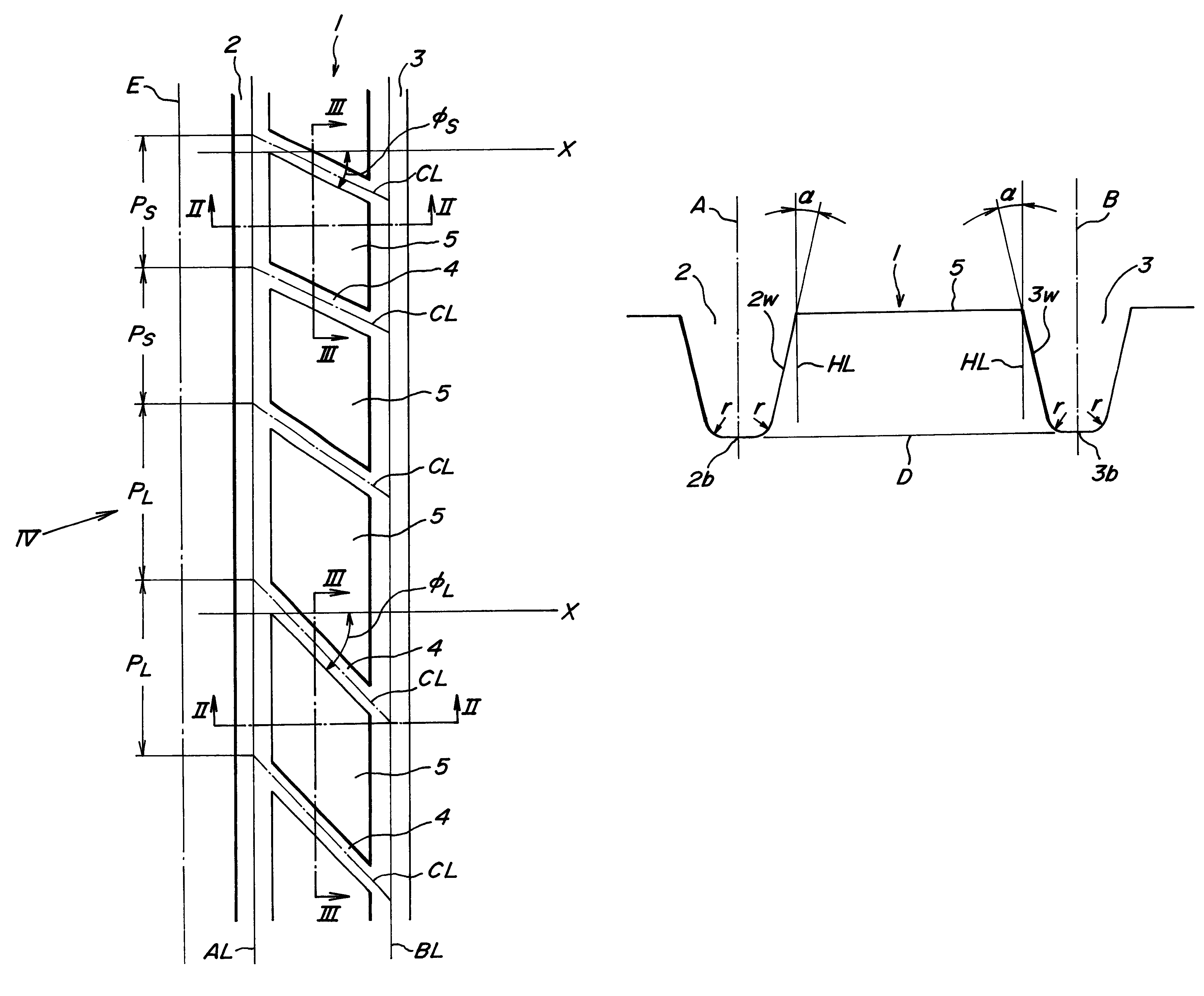
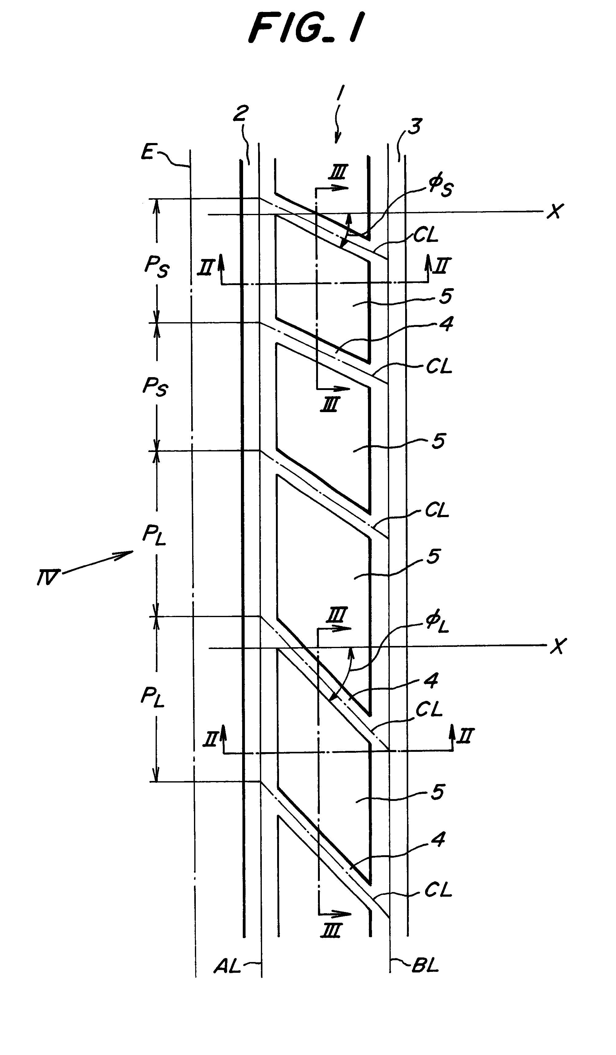
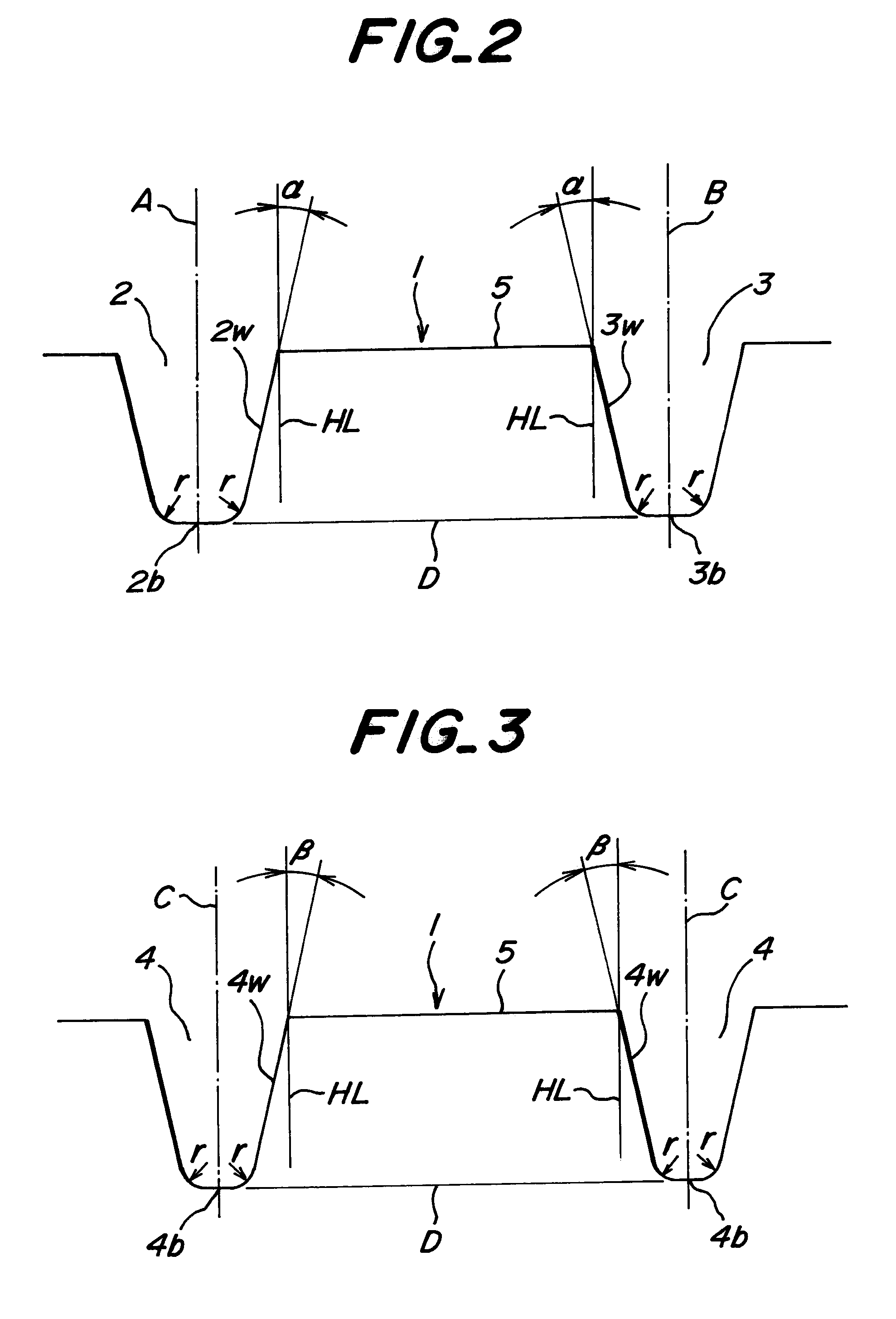
In another preferable embodiment of the invention, the inclination angle of the block wall face directing from the surface of the block toward the bottom of the main groove is gradually decreased over a region ranging from an acute end to an obtuse end in a surface form of each block, which enhances the rigidity of each block in the axial direction and largely contributes to improve both the straight running stability and the steering stability.

Problems solved by technology

The result is that the block row having uniform rigidity zones is not obtained.
Such a change does not count for so much in the low speed to middle speed running of the vehicle, but causes swaying of the vehicle from side to side in the high-speed straight running or a problem of degrading the straight running stability and the steering stability in the cornering at a relatively high speed.
In case of high-performance radial tires to be lately and increasingly mounted onto a high-performance vehicle, it is particularly demanded to highly develop the above both performances, so that the above problem becomes serious.
In the tire having a combination of the first and second cases with the third case wherein the inclination angles of the sub-grooves in all blocks are the same irrespective of the various pitches, there is a risk of simultaneously contacting the sub-grooves the ground in the running under loading, which brings about the occurrence of tire noise through impact sound or the like.

Method used


Image

  • Pneumatic radial tire including blocks having different lengths
  • Pneumatic radial tire including blocks having different lengths
  • Pneumatic radial tire including blocks having different lengths

Examples


Embodiment Construction

The pneumatic radial tire according to the invention (hereinafter abbreviated as a tire) comprises a radial carcass of one or more plies toroidally extending between a pair of bead cores each embedded in a bead portion and a belt reinforcing a tread portion on an outer periphery of the radial carcass though these members are omitted in the drawing.

In FIG. 1 is shown a part of a right-side half of a ground contact region 1 in a tread rubber (omitted in the drawing) constituting an outer part of the tread portion. The tread rubber comprises at least two straight main grooves (hereinafter abbreviated as main groove) 2, 3 (two in the illustrated embodiment) extending along a circumference of the ground contact region 1 in parallel to an equatorial plane E of the tire (shown by a dash-single dot line) and a plurality of lateral sub-grooves 4 (hereinafter abbreviated as sub-groove) 4 extending between these main grooves 2 and 3 and opening to the respective main grooves 2, 3.

As shown in F...


PUM


Abstract

A pneumatic radial tire comprises a radial carcass, a belt, and a row of many blocks having different lengths along a circumference of a ground contact region under pitch variation defined in a tread rubber of the tread portion by at least two straight main grooves and a plurality of lateral sub-grooves extending between the mutual main grooves at an inclination angle of less than 90° with respect to the circumference of the ground contact region, in which the block row satisfies such relationships that an inclination angle phiL of an edge of a long-pitch block is larger than that phiS of an edge of a short-pitch block and an inclination angle alphaL of each block wall face of a long-pitch block is larger than that alphaS of each block wall face of a short-pitch block, or further an inclination angle betaS of a block wall face of a short-pitch block is larger than that betaL of a block wall face of a long-pitch block.

Description

1. Field of the InventionThis invention relates to a pneumatic radial tire, and more particularly to a high-performance pneumatic radial tire capable of considerably improving straight running stability and steering stability while maintaining other properties at a high level and suitable for use in vehicles such as passenger cars.2. Description of Related ArtIn order to enhance the wet skid resistance and resistance to hydroplaning required in a high-performance tire, when a tread pattern formed in a tread rubber is a pattern including block groups defined by at least two main straight grooves extending along a circumference of a ground contact region and lateral sub-grooves arranged therebetween or a block pattern formed over substantially a full ground contact region, a level of noise called as a pattern noise is apt to be increased as compared with that in a rib pattern. Therefore, in order to reduce such a noise level, it is required to adopt a pitch variation wherein pitch len...

Claims


Application Information

Patent Timeline
IPC IPC(8): B60C11/00B60C11/13B60C11/11B60C11/03B60C9/08
CPCB60C11/0318B60C11/1315B60C11/13B60C11/11
Inventor KANEKO, TAKASHIYAMAYA, KENJIRO
Owner BRIDGESTONE CORP
Learn More