Mass customization telecommunications equipment rack

a technology for telecommunication equipment and racks, applied in the direction of dismountable cabinets, electrical apparatus casings/cabinets/drawers, instruments, etc., can solve the problems of affecting the service life of telecommunication equipment, the mounting holes or mounting apertures of conventional equipment racks are often not suitable for digital telecommunication equipment, and the equipment cannot be easily mounted

Inactive Publication Date: 2002-01-15
NEWTON INSTR
View PDF15 Cites 25 Cited by
  • Summary
  • Abstract
  • Description
  • Claims
  • Application Information

AI Technical Summary

Problems solved by technology

As is also well-known in the telecommunications industry, unequal flange equipment racks or bays have previously been constructed to accommodate traditional non-digital equipment, and the slightly wider digital telecommunications equipment does not readily mount in conventional unequal flange equipment racks.
The problem with designing new wider equipment racks for the digital equipment is that the horizontal space between the upright supports must be increased by 0.25 inches but the horizontal spacing between the mounting holes must remain the same as prior unequal flange equipment racks in which the mo

Method used


Image

  • Mass customization telecommunications equipment rack
  • Mass customization telecommunications equipment rack
  • Mass customization telecommunications equipment rack

Examples


Embodiment Construction

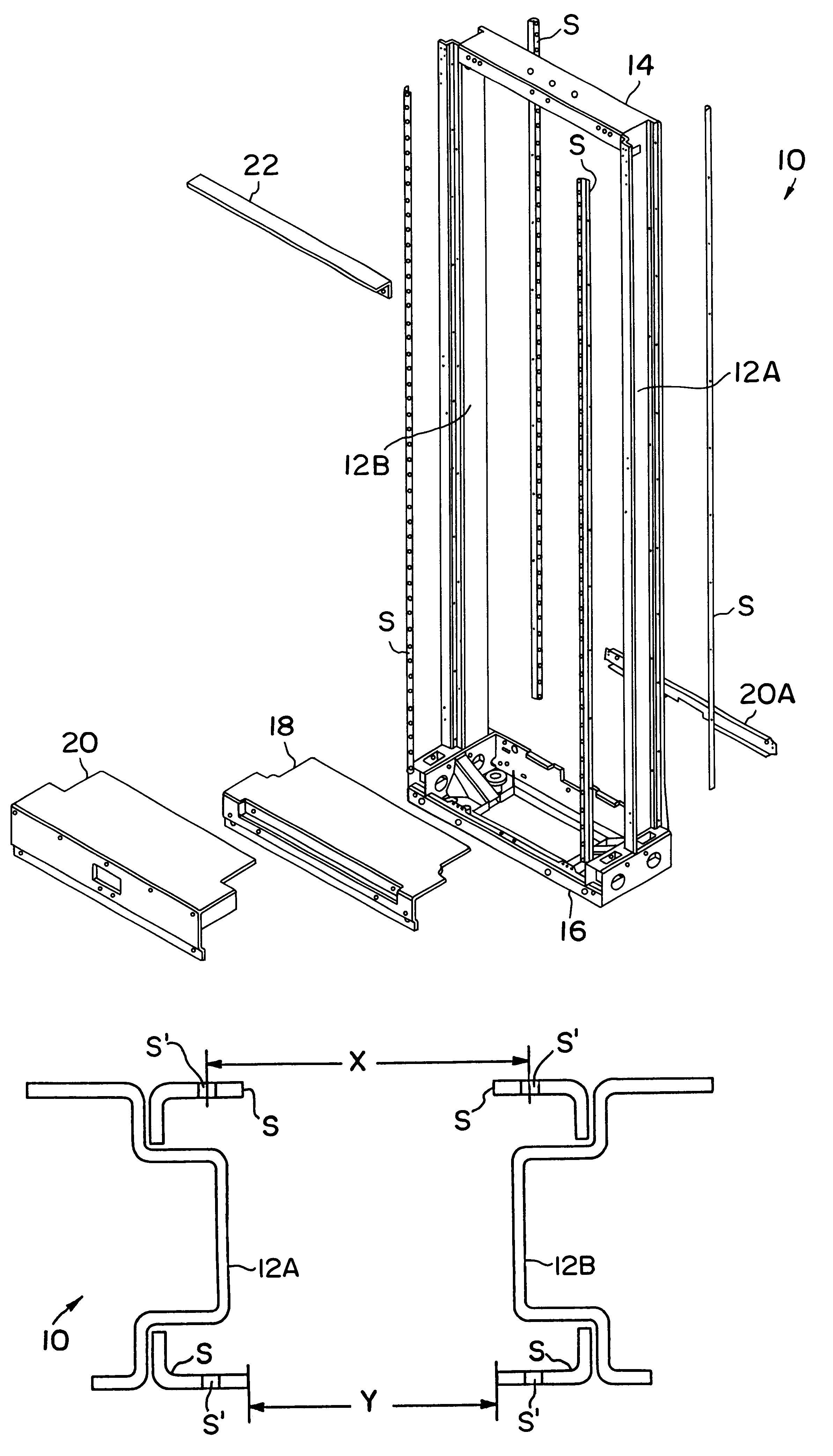
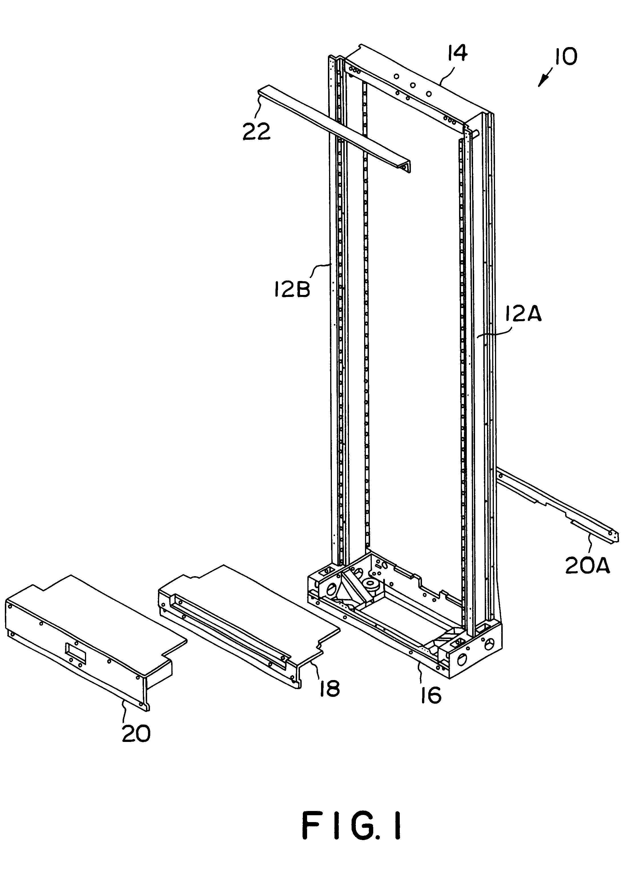
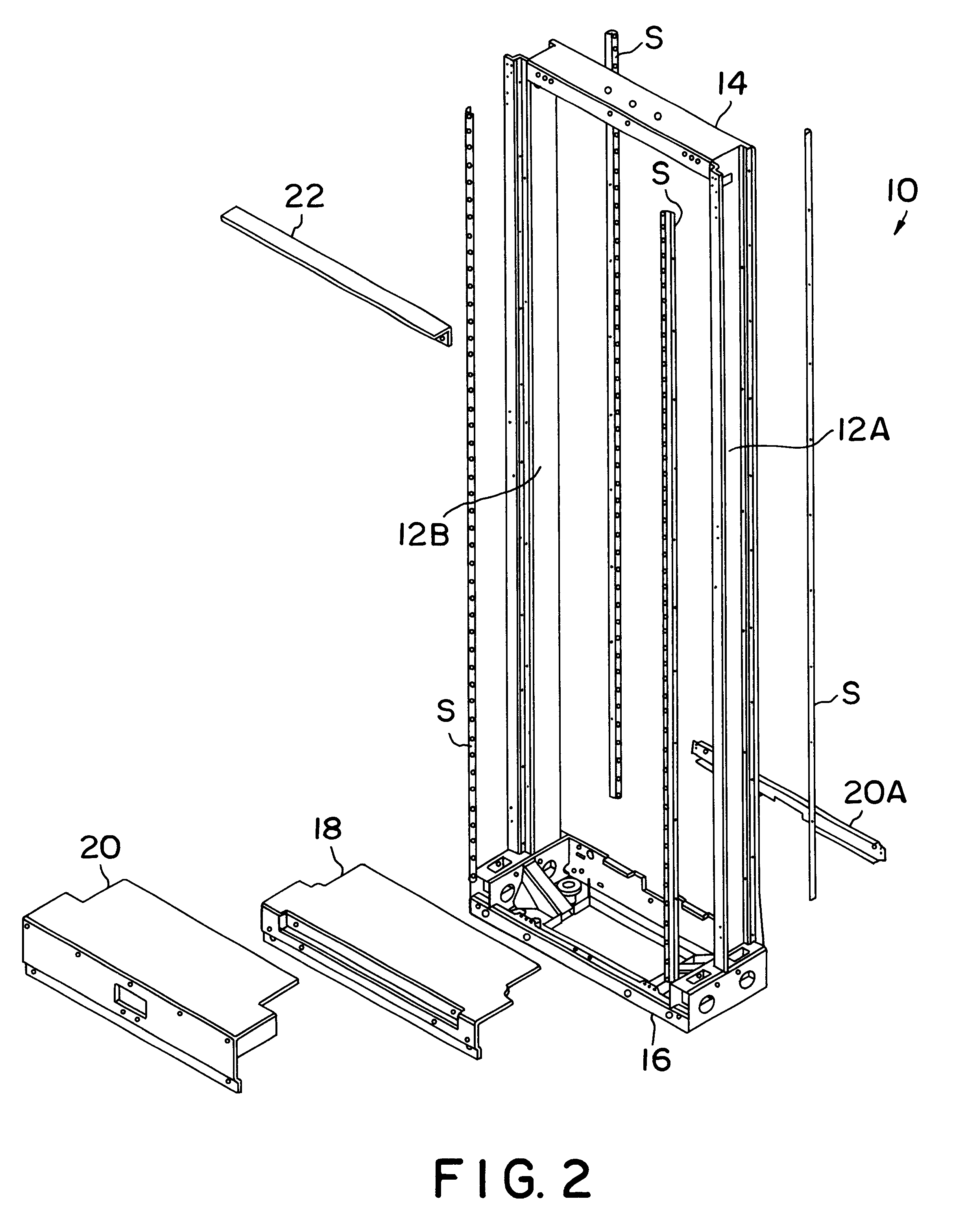
To better explain and to reiterate the functionality of the present invention, reference is now made to FIG. 6A of the drawings illustrating a cross-sectional view of equipment rack 10 (the embodiment of the invention described hereinabove) constructed from two upright metal channels 12A, 12B and having mounting strips S affixed (typically by riveting) thereto. Mounting holes or apertures S' are shown therein for better clarity of understanding. As can be noted with reference to FIG. 6A, distance X indicates the equipment mounting hole distance and distance Y indicates the width of the equipment mounting space or aperture. Traditionally, distance Y is 21.5 inches or 17.5 inches, and traditionally distance X is 22.312 (22 5 / 16) inches or 18.312 (18 5 / 16) inches. As is known to those familiar with telecommunications equipment racks, digital telecommunications equipment requires the same X value but necessitates an additional 0.25 inches in the Y value. This has posed a considerable di...


PUM


Abstract

A rack assembly for mounting telecommunications equipment is provided which will accommodate both Network Bays and UFER Bays and which provides mounting strips secured at the front and rear comers of the upright channels to better accommodate mounting digital equipment in the rack assembly.

Description

The present invention relates to racks or bays used primarily for mounting and housing telecommunications equipment, and more specifically to an improved rack for mounting telecommunications equipment which allows for mounting digital equipment in the rack and the selection of either a Network Bay base or a UFER base in accordance with customer order.RELATED ARTTelecommunications equipment racks or bays are typically installed in controlled environment vaults, central switching offices, and remote switch buildings. As known to those in the telecommunications field, equipment racks or bays can be ordered in many different sizes and configurations. Generally speaking, unequal flange equipment racks (UFERs) can be ordered with either a relatively lower bottom profile Network Bay base or with a relatively higher profile UFER base. Further, unequal flange equipment racks or bays are manufactured in a variety of widths and heights in order to accommodate the needs of customers. As is also...

Claims


Application Information

Patent Timeline
IPC IPC(8): H05K7/18
CPCH05K7/186
Inventor WALTER, JONATHAN T.CAUDILL, BRYAN C.REECE, GILBERT W.
Owner NEWTON INSTR
Why Eureka
Try Eureka