Electrical coupler for detachable interconnection between a main unit and an external unit

Inactive Publication Date: 2002-01-15
MATSUSHITA ELECTRIC WORKS LTD
View PDF15 Cites 21 Cited by
  • Summary
  • Abstract
  • Description
  • Claims
  • Application Information

AI Technical Summary

Problems solved by technology

However, this involves the use of the separate parts and therefore complicates the assembly

Method used


Image

  • Electrical coupler for detachable interconnection between a main unit and an external unit
  • Electrical coupler for detachable interconnection between a main unit and an external unit
  • Electrical coupler for detachable interconnection between a main unit and an external unit

Examples


first embodiment

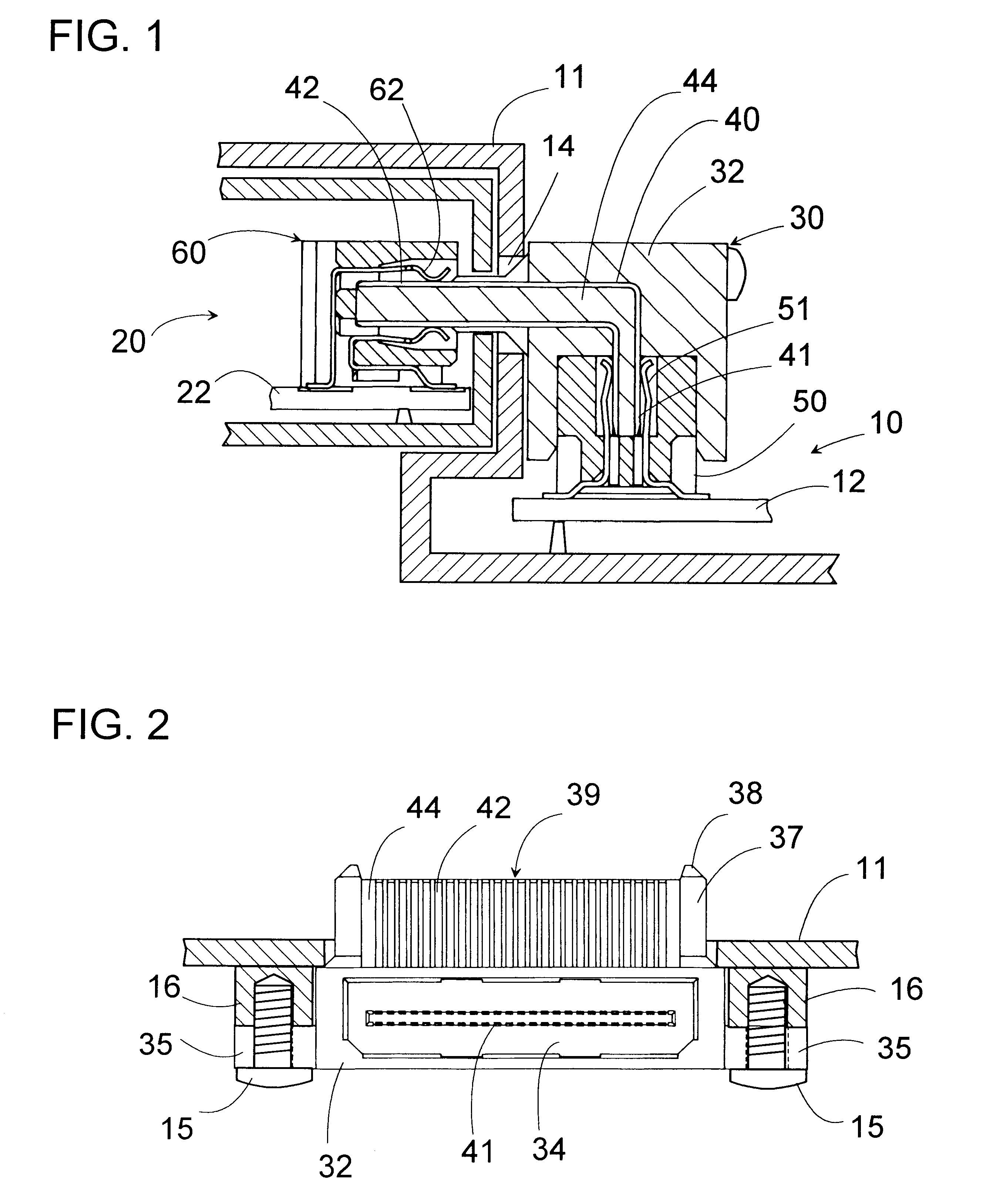
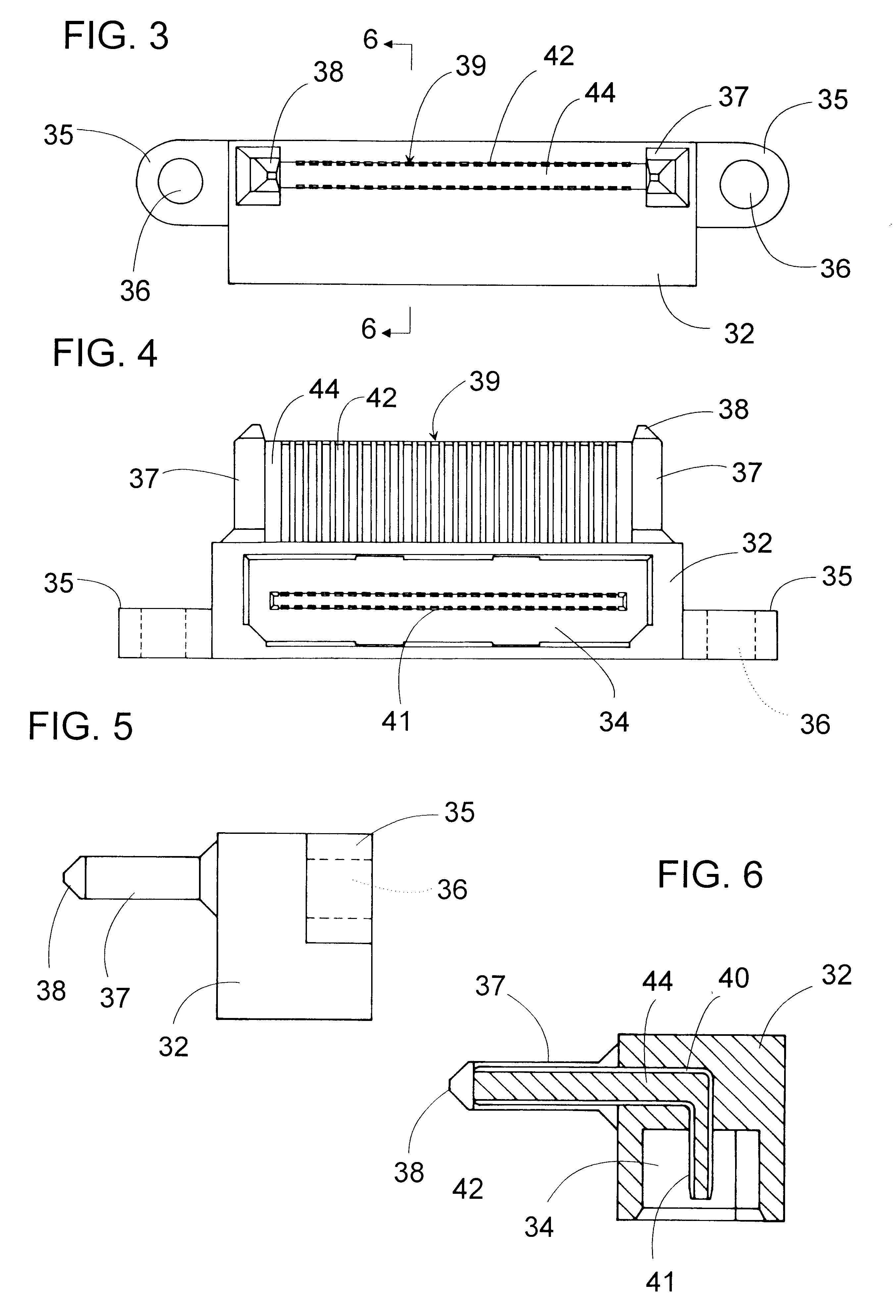
Referring now to FIGS. 1 to 6, there is shown an electrical coupler in accordance with the present invention. The coupler 30 is intended for detachable electrical connection between a main unit 10 and an external unit 20, for example, between a hand-held computer main unit and a plug-in type external CD-ROM unit. In this regard, the coupler 30 includes a terminal connector 39 which is secured to an enclosure 11 or supporting structure of the main unit 10 at a suitable level for detachable connection to the external unit 20, and an array of first terminal ends 41 for internal connection with a main circuit board 12 mounted within the main unit 10. The coupler 30 has a header 32 of a dielectric hard material carrying a plurality of hard conductors 40 of a generally L-shaped configuration each defining at its opposite ends the first terminal end 41 and a second terminal end 42. The second terminal ends 42 are arranged in an array to define the terminal connector 39 for the external uni...

fifth embodiment

FIG. 19 shows an electric coupler in accordance with the present invention which utilizes a flexible tape 90 for height adjustment of a header 32E relative to the main circuit board 12E. The coupler includes, in addition to the header 32E integrally supporting the array of the second terminal ends 42E, a sub-header 80 integrally supporting the array of the first terminal ends 41E which are interconnected to the array of the second terminal ends by the conductors 40E carried partly on the flexible tape 90. Thus, the header 32E can be fixed to the wall of the enclosure at a designated height, while making an internal connection through the flexible tape 90 to the main circuit board 12E fixed in the enclosure. Like parts are designated by like numerals with a suffix letter of "E". The header 32E has integrally molded mount flanges for securing the header 32E to the enclosure wall of the main unit.

FIG. 20 shows an electric coupler in accordance with a sixth embodiment of the present inv...


PUM


Abstract

An electrical coupler which is capable of being easily assembled into a main unit for electrically detachable interconnection of an external unit to the main unit. The coupler includes a dielectric header which carries an array of first terminal ends and an array of second terminal ends which are engageable with an arrays of first contacts of the main unit and an array of second contacts of the external unit for establishing an electrical interconnection. The header is made of a rigid material which integrally supports the array of the second terminal ends to define thereat a terminal connector responsible for detachable connection to the external unit. The header is molded to have a mount flange as an integral part for securely fixing the header to an enclosure of the main unit. A height adjusting mechanism is provided to vary a vertical position of the header relative to a main circuit board with which the first terminal ends are connected internally of the main unit, adjusting a height of the terminal connector from the main circuit board. Thus, the electrical coupler can be successfully assembled into the main unit with the terminal connector located at a suitable position for connection with the external unit, yet assuring to easily fix the terminal connector at that position to the enclosure in such a manner as to well bear the pulling and pushing force exerted at the time of connecting and disconnecting the external unit to and from the terminal connector.

Description

1. Field of the InventionThe present invention is directed to an electrical coupler for detachable interconnection between two electrical units, one being a main unit and the other being an external unit which is additional and detachable to the main unit.2. Description of the Prior ArtIn the field of computer devices, particularly hand-held computers, the computers are usually accompanied with an optional device such as a CD-ROM unit or the like external unit which is to be coupled and decoupled to and from to a main unit of the computer, as required by an user. To meet this requirement, the main unit of the computer is provided with a terminal connector for detachable connection to the external unit. The terminal connector is internally connected to a circuit board incorporated in the main unit for connection with a corresponding control circuit that the computer inherently includes. In order to deal with varying locations of the terminal connector which are determined by other de...

Claims


Application Information

Patent Timeline
IPC IPC(8): H01R12/00H01R31/06H05K1/00H01R12/71
CPCH01R12/727H01R12/7082H01R31/06
Inventor HASHIMOTO, SHUNSUKEOKURA, KENJI
Owner MATSUSHITA ELECTRIC WORKS LTD
Why Eureka
Try Eureka