Indicator light with uniform illuminating surface for a motor vehicle

a technology of indicator lights and motor vehicles, applied in the direction of fixed installation, transportation and packaging, light and heating equipment, etc., can solve the problem that the light does not solve the problem completely

Inactive Publication Date: 2002-01-22
VALEO VISION SA
View PDF7 Cites 21 Cited by
  • Summary
  • Abstract
  • Description
  • Claims
  • Application Information

AI Technical Summary

Benefits of technology

one of the faces of the cup is able to provide the desired distribution of the light in one of the horizontal and vertical directions, and the other face of the cup is able to provide the desired distribution of the light in the other direction;
the outer face of the cup is able to provide the desired distribution of the light in the direction corresponding to the larger dimension of the optical plate;

Problems solved by technology

When optical configurations of the Fresnel lens type are used, in combination with the lamp, the same kind of problem is encountered, the central region of the lens emitting a flux density which is appreciably greater than its peripheral region.
However, this known light does not completely solve the problem of the lack of uniformity, in the sense that the arrangements for straightening the light which are provided on the plate exhibit coefficients of transmission of the light which vary greatly from one place to another, and in particular according to the amount of straightening demanded, such that, ultimately, such a light retains an appreciably greater density of luminous flux in line with the lamp than towards the lateral edges of the lamp.
Furthermore, the teachings of this document apply in a limited away to a light of restricted height, and give no indication making it possible to deal with the case of a light the illuminating surface of which exhibits not only a substantial width but also a substantial height.

Method used


Image

  • Indicator light with uniform illuminating surface for a motor vehicle
  • Indicator light with uniform illuminating surface for a motor vehicle
  • Indicator light with uniform illuminating surface for a motor vehicle

Examples


Embodiment Construction

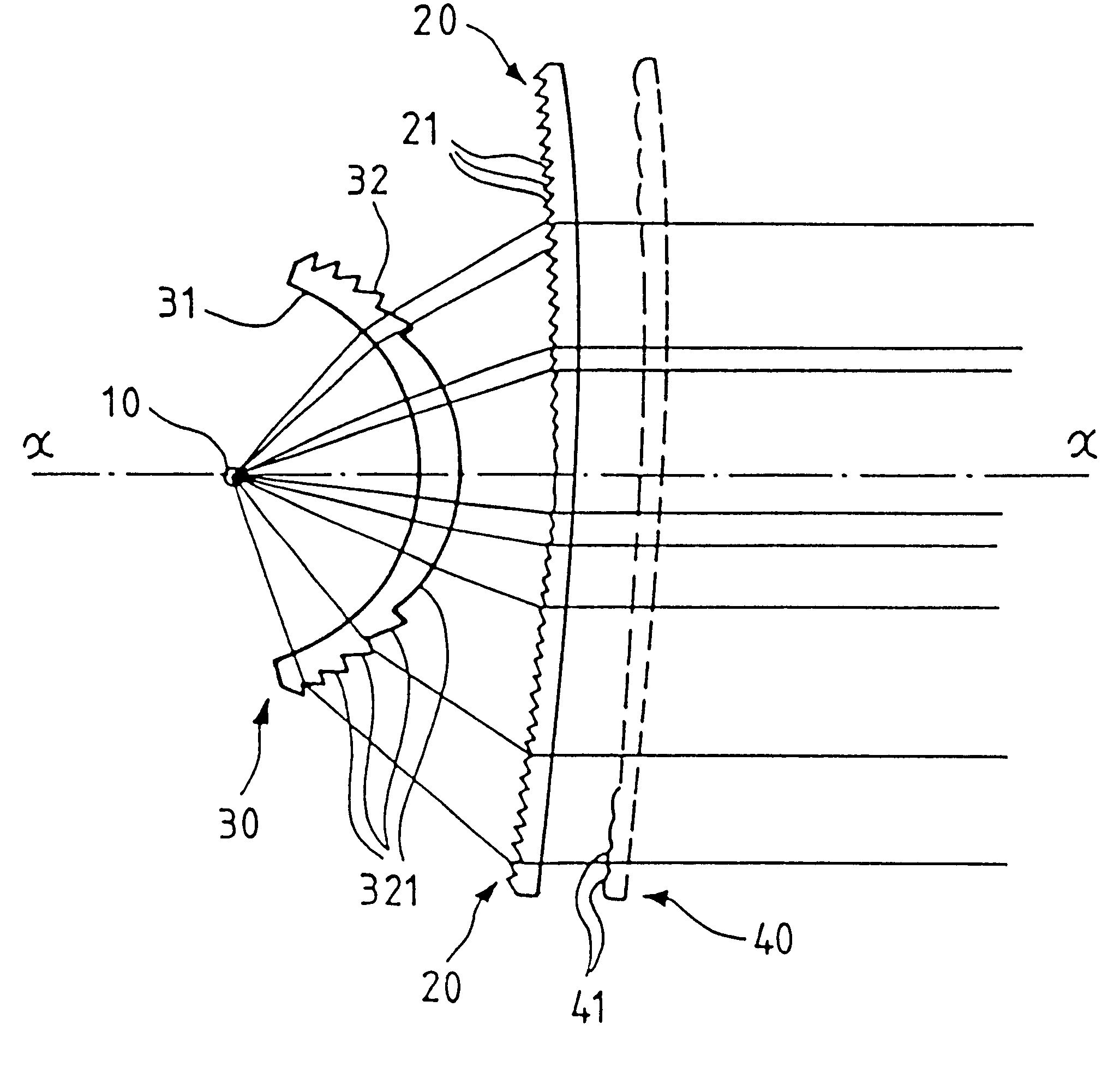
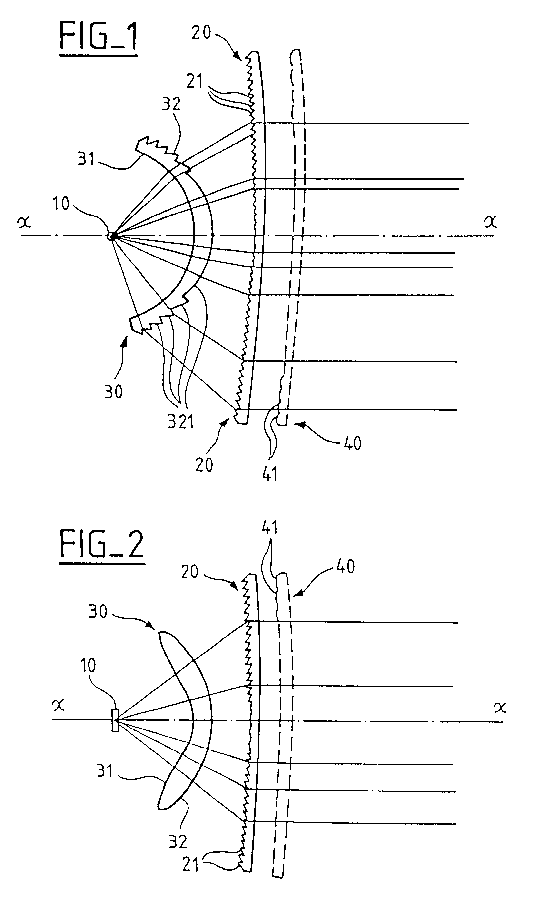
Referring to the drawings, an indicator light comprises a light source 10, here the elongate filament of a standard indicator lamp, a flux-distributing element 30 in the general shape of a cup, a flux-straightening element 20 in the general shape of a plate, and a bezel 40 extending along and outside the plate 20. The light also comprises, in a way which is not represented but which is well known in itself, a base, a lamp holder, a connector, etc.

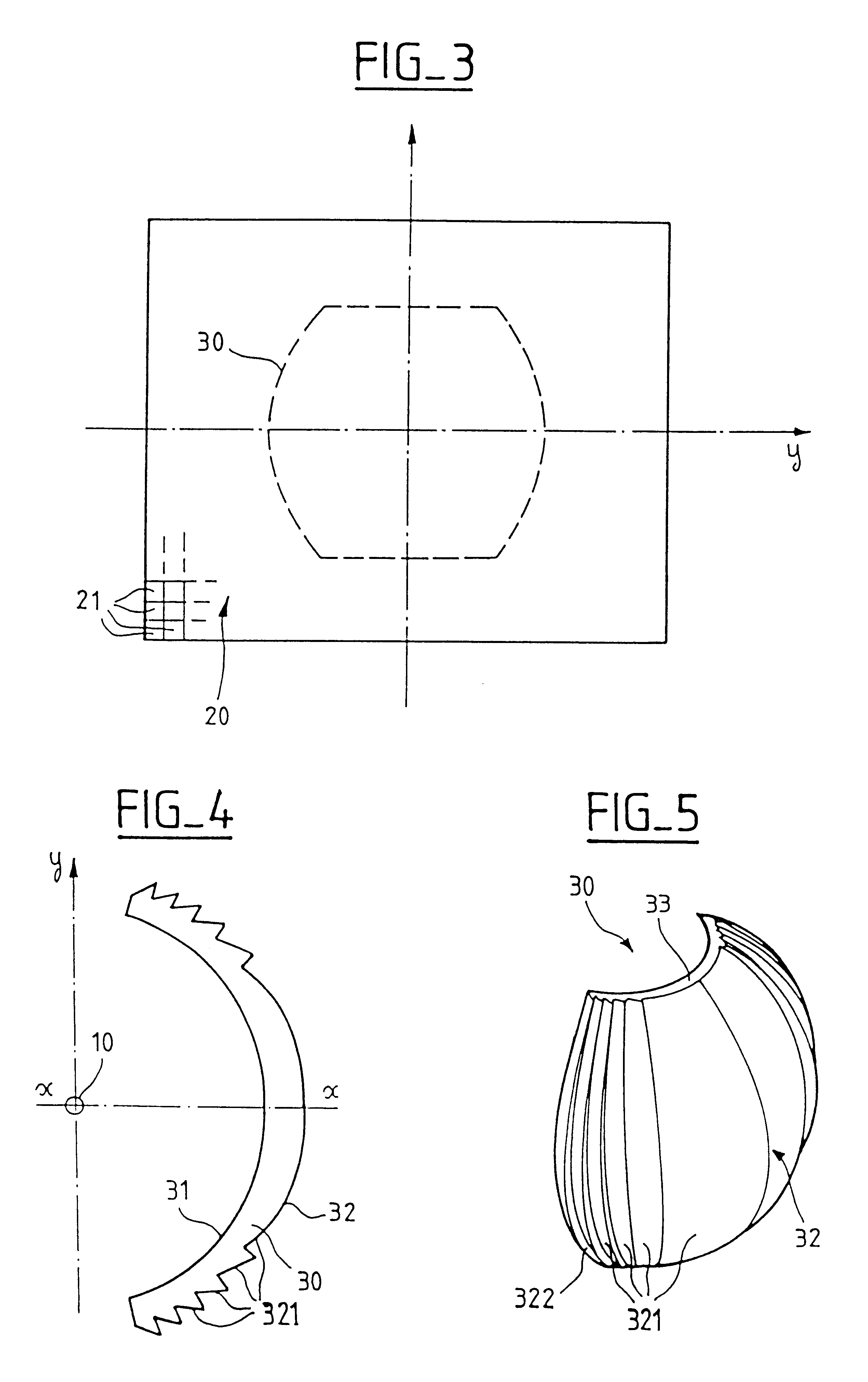
This light is represented in a right-angled reference system (0, x, y, z), x being the optical axis of the light, z being vertical and y perpendicular to x and to z, and 0 being situated at the center of the source 10.

The optical plate 20 and the bezel 40 possess dimensions in terms of height and width which are close to one another, and more generally of the same order of magnitude, that is to say that, when it is desired to obtain a uniform area of brightness at the exit from the light, the problems of uniform distribution of the illumina...


PUM


Abstract

An indicator light comprises a source, an optical plate adapted to straighten out the incident light towards an average direction generally parallel to an optical axis, and a flux-distributing and recuperating cup interposed between the source and the plate in order to distribute the light over the inner surface of the plate. According to the invention, the optical plate has a height and a width of the same order of magnitude and possesses optical configurations having varied coefficients of transmission of the light, and the cup provides a given distribution of the light, both in the horizontal direction and in the vertical direction, which takes account of said coefficients. As a result, an illumination is obtained at the exit from said plate which is essentially constant in the horizontal direction as well as in the vertical direction.

Description

The present invention relates to indicator lights for motor vehicles.There is currently an increasing preoccupation with the production of an indicator light which, when it is illuminated, exhibits an illuminating surface which is as uniform is possible, and does so for any observation position in the luminous field of the lamp.The deficiencies of known indicator lights equipped with a single source (filament-type lamp) interacting with a rear recuperator mirror are an excess of light intensity in that region of the bezel which is situated in line with the lamp, and which is exposed to the greatest density of luminous flux. When optical configurations of the Fresnel lens type are used, in combination with the lamp, the same kind of problem is encountered, the central region of the lens emitting a flux density which is appreciably greater than its peripheral region.There is also known, from the document FR-A-2 614 969 in the name of the Applicant, an indicator light which is designed...

Claims


Application Information

Patent Timeline
Patent Type & Authority Patents(United States)
IPC IPC(8): F21V9/08F21V5/00F21V9/00F21S8/10F21V17/00F21W101/10F21W101/14F21Y101/00
CPCF21S48/2218F21S48/2212F21S43/255F21S43/26
Inventor GODBILLON, VINCENTGASQUET, JEAN CLAUDE
Owner VALEO VISION SA
Why Eureka
Try Eureka