Restraint-type differential relay

a relay and resistance technology, applied in circuit-breaking switches, circuit-breaking switches for excess current, electrical apparatus, etc., can solve problems such as ct going into saturation, ct inaccuracy, and course is quite undesirable, and achieve the effect of preventing a tripping signal

Inactive Publication Date: 2002-01-22
SCHWEITZER ENGINEERING LABORATORIES
View PDF1 Cites 73 Cited by
  • Summary
  • Abstract
  • Description
  • Claims
  • Application Information

AI Technical Summary

Benefits of technology

Accordingly, the present invention is a differential relay for protecting a power system apparatus in a power system, the power system apparatus having a power line input and a power line output, comprising: means for detecting the power signal current present on the power line input and the power line output, respectively; means for recognizing a fault condition in the power system external to the power system apparatus; means for preventing a tripping signal in response to the external fault condition for a selected period of time; and means for recognizing an internal fault during said selected period of time, including the evolution of said external fault into an internal fault, and for permitting a tripping action during said selected period of time.

Problems solved by technology

When one Ct does not produce the primary current accurately, inaccurate, i.e. fictitious, current is presented to the differential relay which produces an inaccurate result.
A typical cause of CT inaccuracy is the CT going into saturation when a fault occurs.
When the CT for the I.sub.2 (outgoing) current saturates, for instance, the I.sub.2 value will be incorrect, and the differential relay may declare an internal fault condition, with a subsequent inappropriate raly operation (trip).
This of course is quite undesirable.
These solutions, however, while providing improved operation in some situations, fail to present relay misoperation in other situations.
Further, with respect to the first solution, the trip logic for the differential relay is completely blocked during the time when the second harmonic is above a set threshold.
The relay, however, cannot recognize an external fault which evolves to an internal fault or an internal fault which develops independently during the blocking time.
This delays unnecessarily the recognition and response to an internal fault.
However, such a combined arrangement slows down the operation of the differential relay, which can otherwise be quite fast in operation.
Further, the combination cannot detect high resistance faults for incoming and outgoing currents which are 180.degree. out of phase.

Method used


Image

  • Restraint-type differential relay
  • Restraint-type differential relay
  • Restraint-type differential relay

Examples


Embodiment Construction

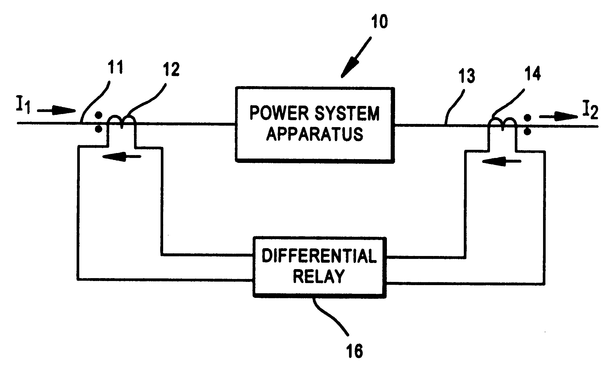
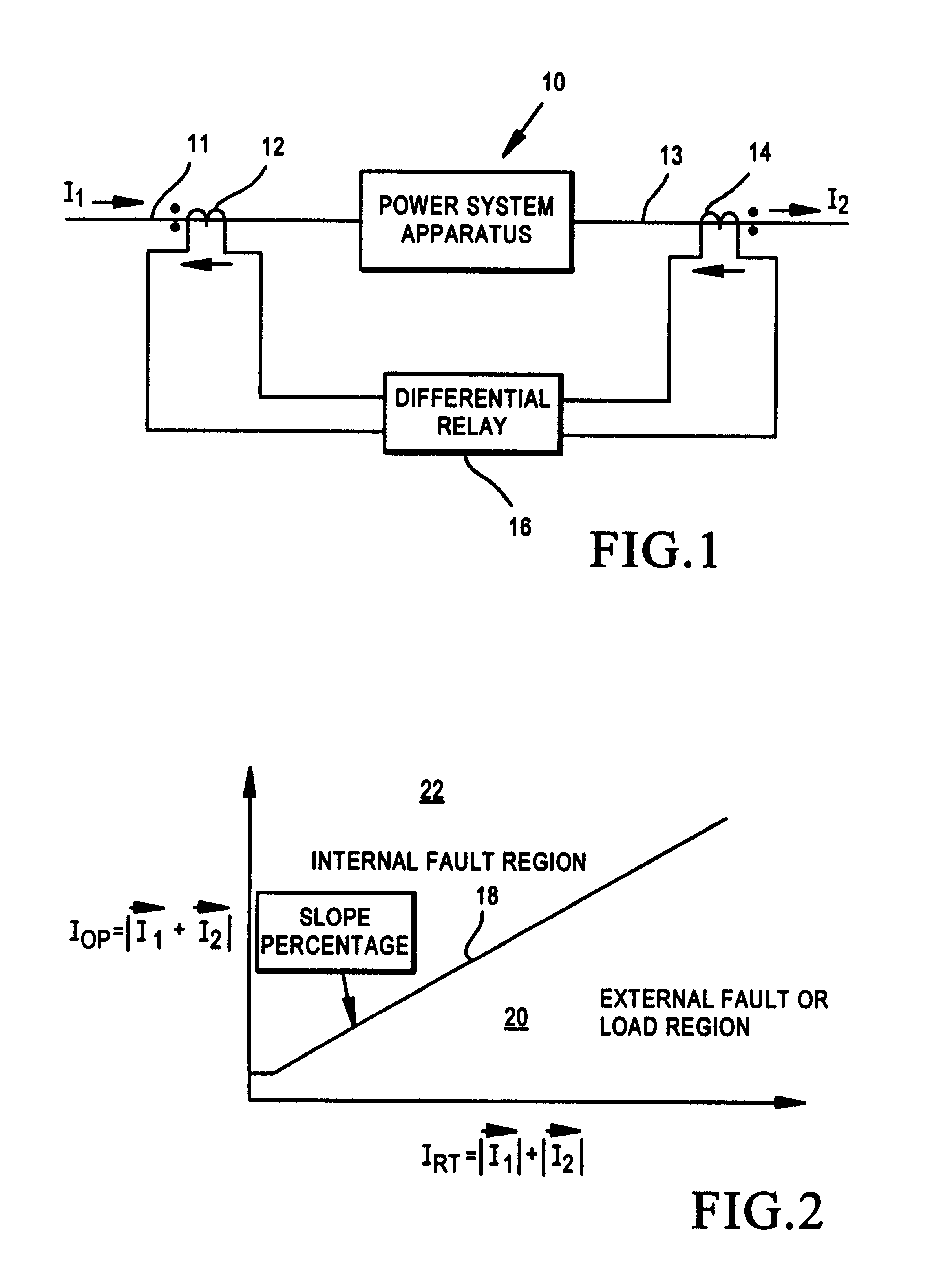
Unlike previous restraining-type differential relays, which, upon recognition of an external fault, absolutely block the differential relay from operating (tripping) for a fixed period of time, e.g. 7 cycles, the differential relay of the present invention, upon recognition of an external fault, is designed to prevent relay operation in response to the external fault, but also to permit relay operation if and when the external fault evolves into an internal fault or if and when an internal fault occurs independently within the time that the relay is being blocked in responding to the external fault. The relay is thus in effect "desensitized" from an absolute blocking approach by being responsive to the internal faults while maintaining security (avoiding tripping) in response to the external fault.

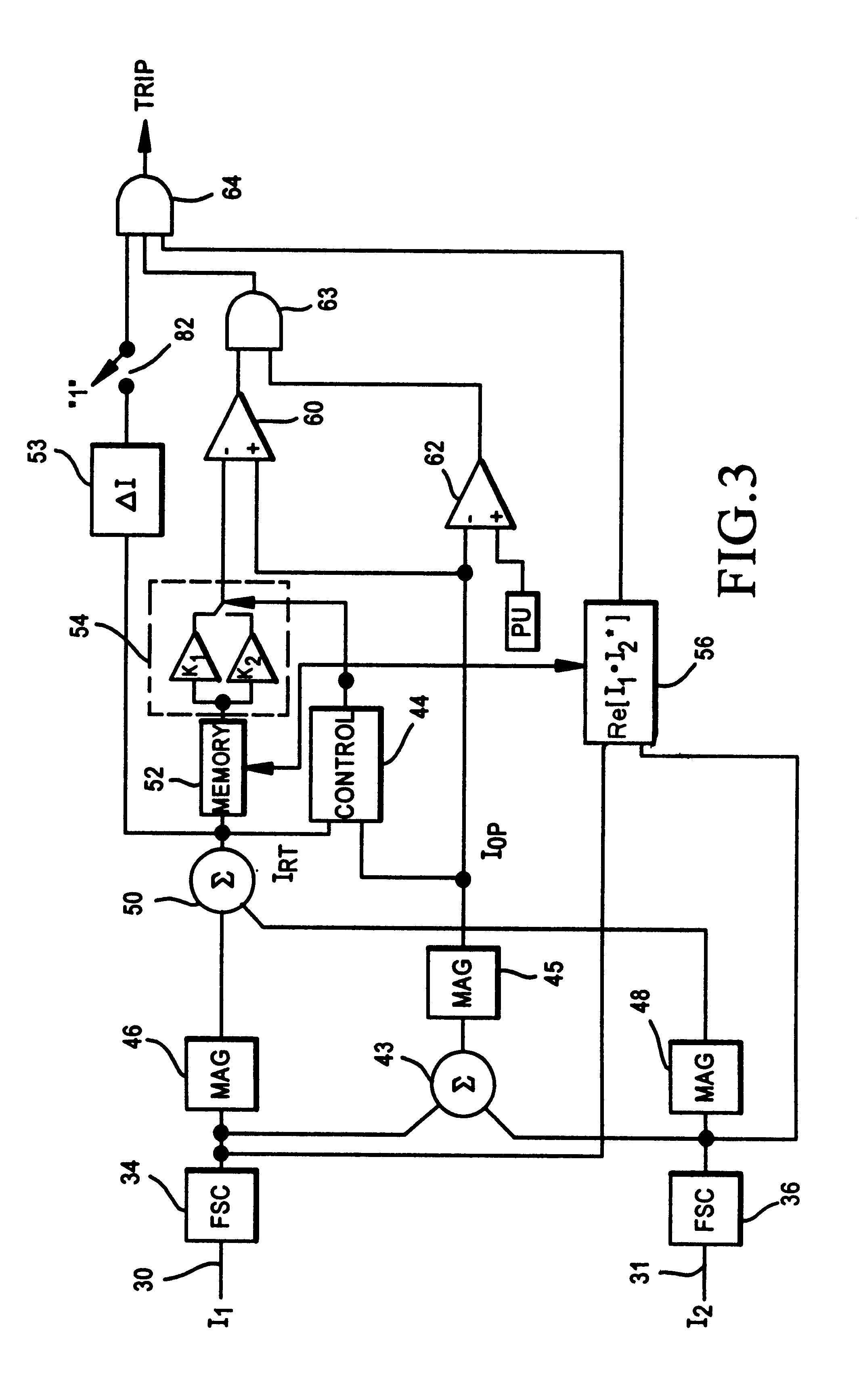
The present invention is thus a fundamentally different restraining differential relay. A block diagram of the new restraining differential relay is shown in FIG. 3. The two current inputs...


PUM


Abstract

A differential relay for protecting a power apparatus portion of a power system, such as a bus line, includes incoming and outgoing power lines on which incoming and outgoing currents are present. The incoming and outgoing currents of each phase are applied through current transformers and then through filtering and normalizing circuits prior to application to the differential relay. The differential relay includes a circuit for determining the presence of an external fault, and maintains security by avoiding a tripping action of the relay for said external faults. Further, the relay includes circuits which in response to the external fault evolving to an internal fault alters the operation of a portion of the relay, by increasing the gain for the restraint current, enabling a directional element for supervision of the differential relay, and for extending the immediate post-fault value of restraint current, and adding a time delay for a selected period of time, all of which are used to identify an external fault evolving into an internal fault.

Description

This invention relates generally to differential relays which are used for protection of power system apparatus, and more specifically concerns such a differential relay which is capable of responding to a fault internal to the power system apparatus during the time it is restrained from operating in response to an external fault.Differential relays have been used for many years to protect various power system apparatus, including generators, transformers, power lines and busses, among others. In the basic operation of a differential relay, incoming current to the power system apparatus for each phase (A, B and C) of the power signal is compared against the outgoing current from the power system apparatus. When the two currents are the same for each phase, the power system apparatus is operating properly. However, when an internal fault (internal to the power system apparatus) occurs, the two currents will be unequal, and by processing the two currents properly, an accurate determin...

Claims


Application Information

Patent Timeline
Patent Type & Authority Patents(United States)
IPC IPC(8): H02H3/26H02H3/28H02H3/08
CPCH02H3/283H02H3/081
Inventor GUZMAN-CASILLAS, ARMANDO
Owner SCHWEITZER ENGINEERING LABORATORIES
Why Eureka
Try Eureka