Fence system

Inactive Publication Date: 2002-01-29
ALLIED TUBING & CONDUIT CORP
View PDF15 Cites 42 Cited by
  • Summary
  • Abstract
  • Description
  • Claims
  • Application Information

AI Technical Summary

Benefits of technology

, the present invention comprises a plurality of anchoring posts, a plurality of rails pivotally mounted to the plurality of posts, and a plurality of pickets pivotally mounted to the plurality of rails. To permit pivotal movement of the pickets relative to the rails, a unique grommet is used to mount the pickets to the rails. This unique grommet for fence systems comprises the snap-fitting of two C-shaped grommet pieces, each having a pivot pin, into a pair of opposing holes formed in the square tube pickets. The grommet, which defines a flange, a groove, an

Problems solved by technology

Both of these fence systems, however, are rigid structures and thus are not desirable to install on inclines or non-leve

Method used


Image

  • Fence system
  • Fence system
  • Fence system

Examples


Embodiment Construction

and the preferred embodiment follows, after a brief description of the drawing.

The preferred embodiments of the invention will be described in relation to the accompanying drawings. In the drawings, the following figures have the following general nature:

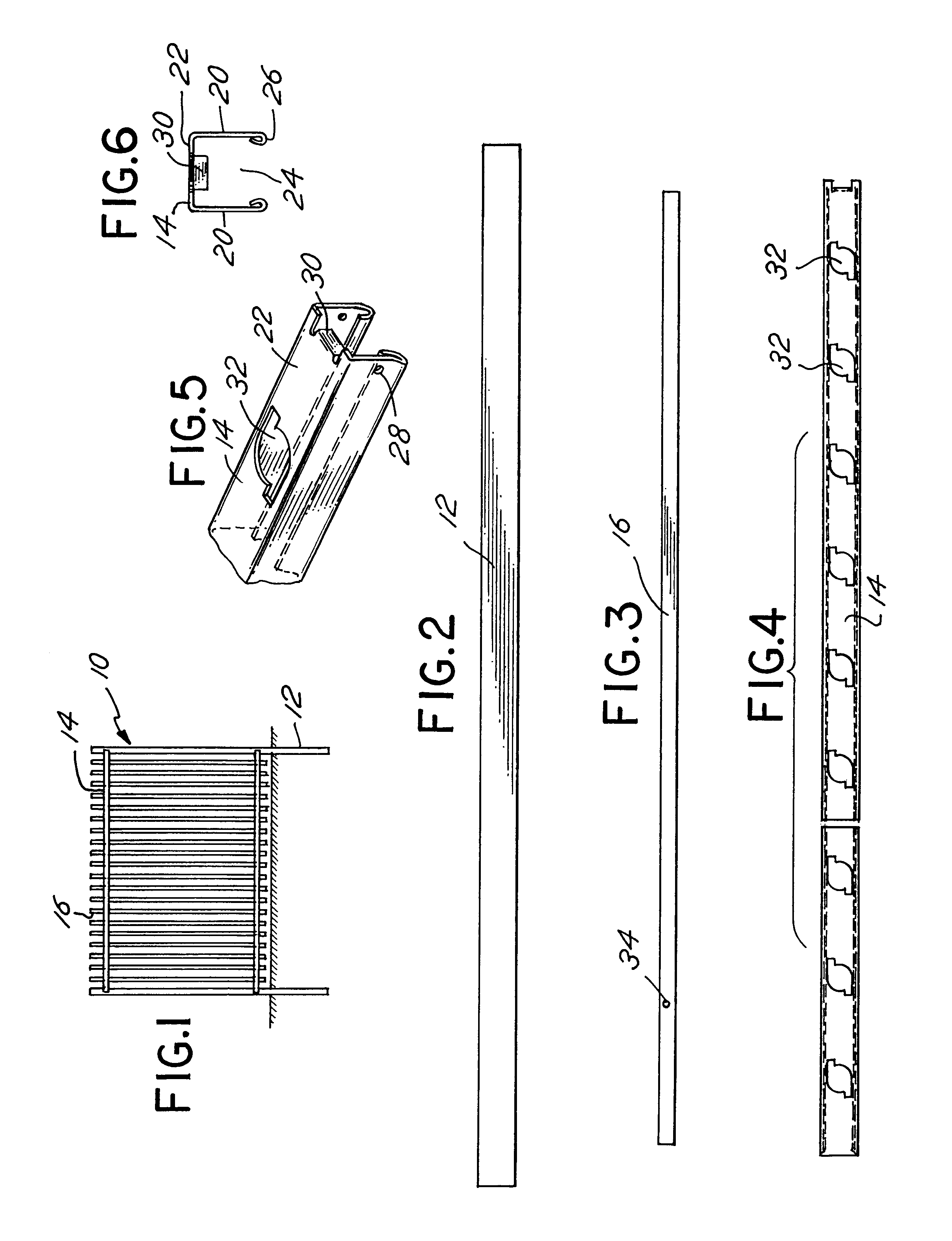
FIG. 1 is a side view of the fence system of the present invention.

FIG. 2 is a side view of the post of the invention of FIG. 1.

FIG. 3 is a side view of the picket of the invention of FIG. 1.

FIG. 4 is a plan view of the rail of the invention of FIG. 1.

FIG. 5 is an isometric view of the rail of FIG. 4.

FIG. 6 is an end view of the rail of FIG. 4.

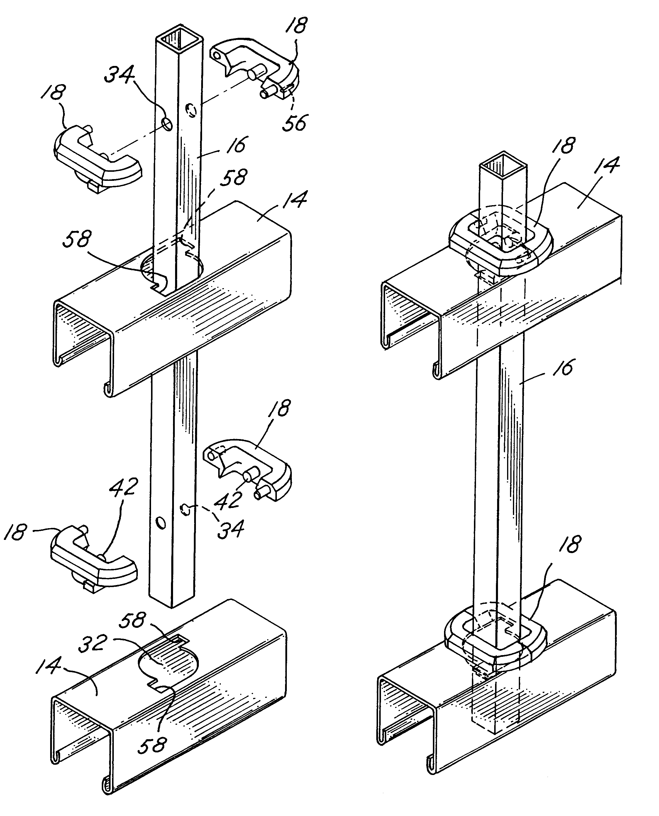
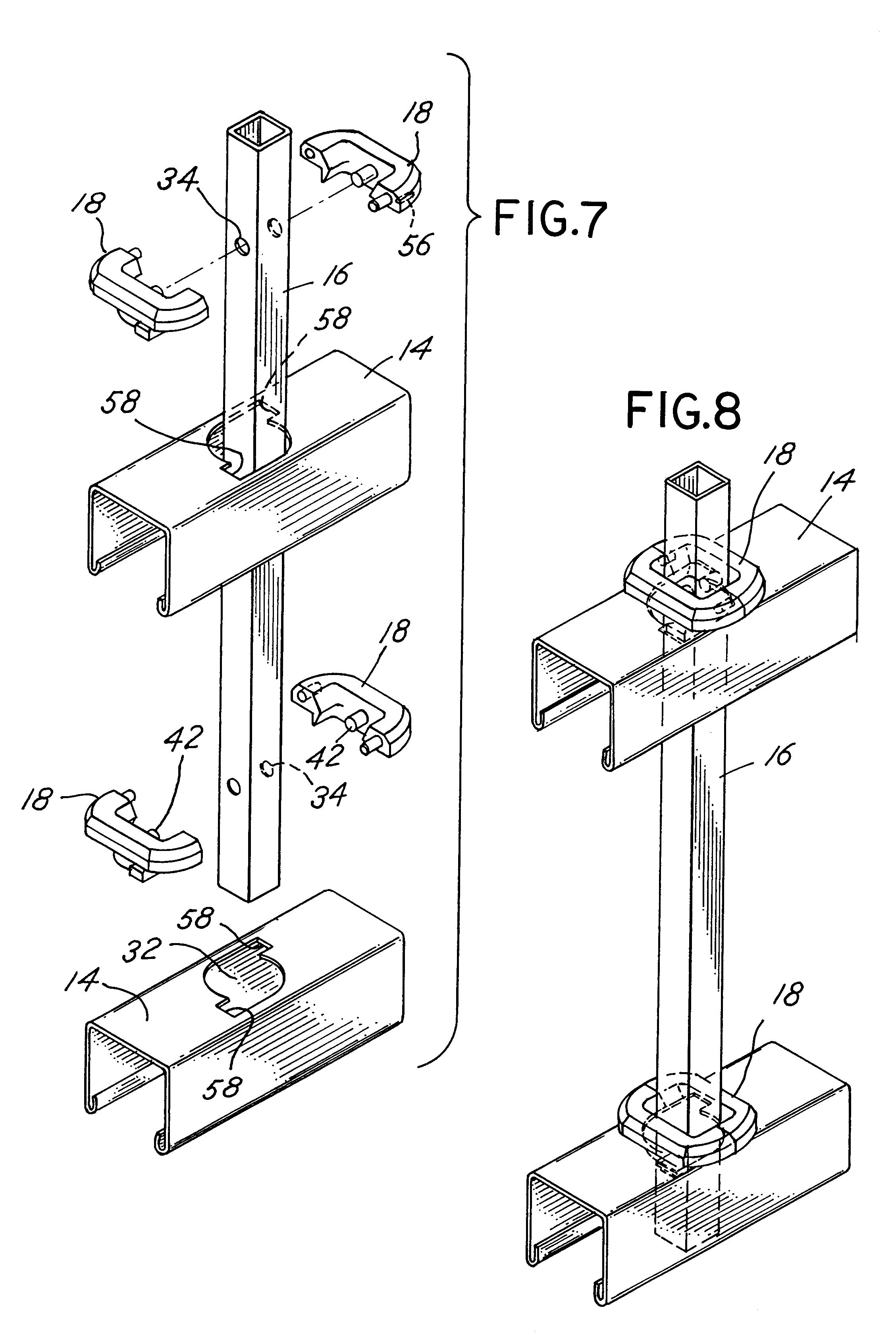
FIG. 7 is an enlarged assembly view of the picket and rail assembly of the present invention.

FIG. 8 is an assembled view of the invention of FIG. 7.

FIG. 9 is an assembled view of the invention of FIG. 8 after the picket has been rotated 90 degrees.

FIG. 10 is an assembled view of the invention of FIG. 9 illustrating the pivotal movement of the rail relative to the picket.

FIG. 11 is an isometric...


PUM


Abstract

An improved picket fence system is disclosed comprising a plurality of vertical posts, a plurality of rails mounted to the posts, and a plurality of pickets pivotally mounted to the plurality of rails. The pickets are pivotally mounted to the rails through the use of a unique grommet assembly that is snap-fitted onto the pickets and is seated in an aperture in the rail. The grommet, which defines a pivot pin, permits the picket to pivot about the pivot pin and thus relative to the rail, thereby providing a unique fence system that may be installed on either a level grade or an incline with minimal, if any, tooling.

Description

1. Field of InventionThe present invention relates in general to fence systems. More specifically, but without restriction to the particular use which is shown and described, this invention relates to an improved ornamental fence system incorporating pivotal pickets which are easily assembled to the rails.2. Description of the Related ArtThe manufacture and assembly of ornamental and security fence systems has been gradually improved upon in the prior art. However, there still remains a need for improved picket fence systems that are mountable on level grades or on inclines, where the pickets need to pivot relative to the rails. Moreover, there is always a need for picket fence systems that are easily installed with minimal parts and tooling. For example, Van Dorn, U.S. Pat. No. 189,543 discloses an early picket fence system having pickets which are installed through openings in the rails and then rotated 90 degrees to lock the picket to the rail. Leone, U.S. Pat. No. 5,150,885 teac...

Claims


Application Information

Patent Timeline
IPC IPC(8): E04F11/18E04H17/14
CPCE04H17/1439
Inventor CONNER, JOHN P.
Owner ALLIED TUBING & CONDUIT CORP
Why Eureka
Try Eureka