Sign hanging device

Inactive Publication Date: 2002-02-05
COON GARY T
View PDF10 Cites 3 Cited by
  • Summary
  • Abstract
  • Description
  • Claims
  • Application Information

AI Technical Summary

Benefits of technology

My invention is designed for attachment to any surface which accepts the adhesion of a strip of metal mounting rail. It combines simplicity of design and function as well as being very easy to use by people of all ages. An advantage is the small linear area required for the point of attachment. Many fastening systems necessitate large bulky mechanisms to secure the sign to the structure. A small length of mounting rail is all my invention needs to form a secure point of attachment.
Most support assemblies for signs are very complicated and cumbersome. They require a great deal of effort and a reasonable level of expertise to assemble. A major advantage of my invention is the simplicity of assembly. Because it is one piece, the user simply slides the dowel rod into the mounting rail in one fluid motion and it is ready for use. Once the sign is attached to the "S" hooks, simply squeeze the "S" hooks closed. If there is not an existing strip of mounting rail, a small strip (supplied with the invention) can quickly be mounted with two screws.
A further advantage is its versatility and portability. It can be removed in just a few seconds. Additionally, it can be displayed in a small area using a vertical post. Used in this fashion, it is ideal for small advertising displays inside a building where it would heretofore be impossible to hang a sign.
Applications for my invention would include a Recreational Vehicle, private residence, garage, dock, horse trailer, horse barns, and stalls. It could be displayed at retail stores, flea markets, race tracks, amusement parks, and sports stadiums. Because of its versatility, it can be displayed indoors as easily as outdoors. Because the weight is supported horizontally, instead of vertically (the support-from-below method), a free-span area is created in which the sign can hang freely.

Problems solved by technology

Attaching a horizontal sign to a vertical edifice is often cumbersome and difficult.
The use of multiple parts increases the likelihood of failure for one of the individual components and hence the degradation and eventual failure of the entire support mechanism.
Additionally, the use of multiple parts make the assembly and installation process more difficult and increase the likelihood of one of the parts being damages or lost.
However, in this arrangement, the sign can only be suspended vertically from the wall.
Thus, it can not be viewed from a right-angle to the wall.
It has the same viewing drawbacks as the Taylor patent and the sliding process, upon insertion and removal, is subject to bending or breaking the rails on both the bracket and sign.
Many fastening systems necessitate large bulky mechanisms to secure the sign to the structure.
Most support assemblies for signs are very complicated and cumbersome.
They require a great deal of effort and a reasonable level of expertise to assemble.

Method used


Image

  • Sign hanging device
  • Sign hanging device
  • Sign hanging device

Examples


Embodiment Construction

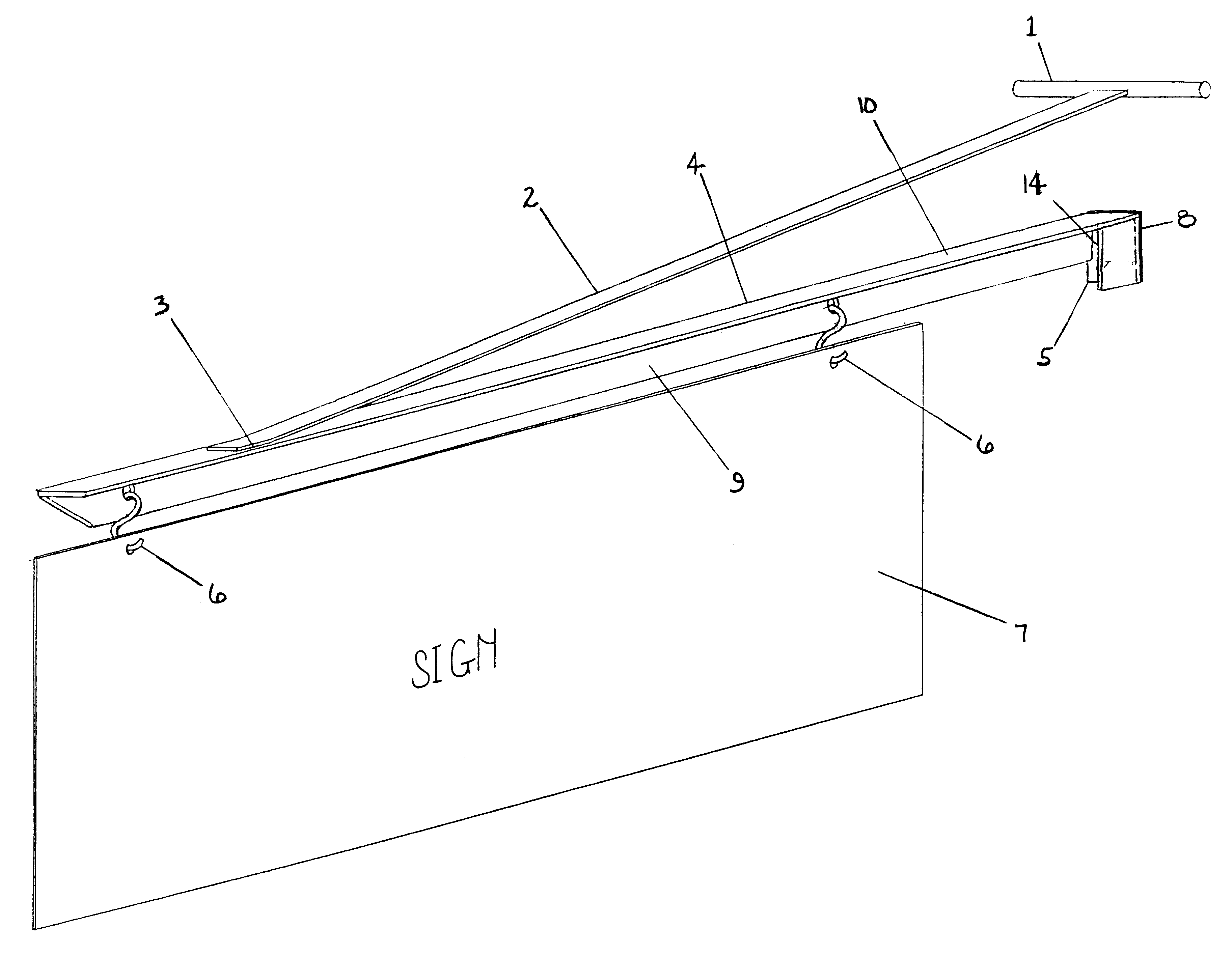
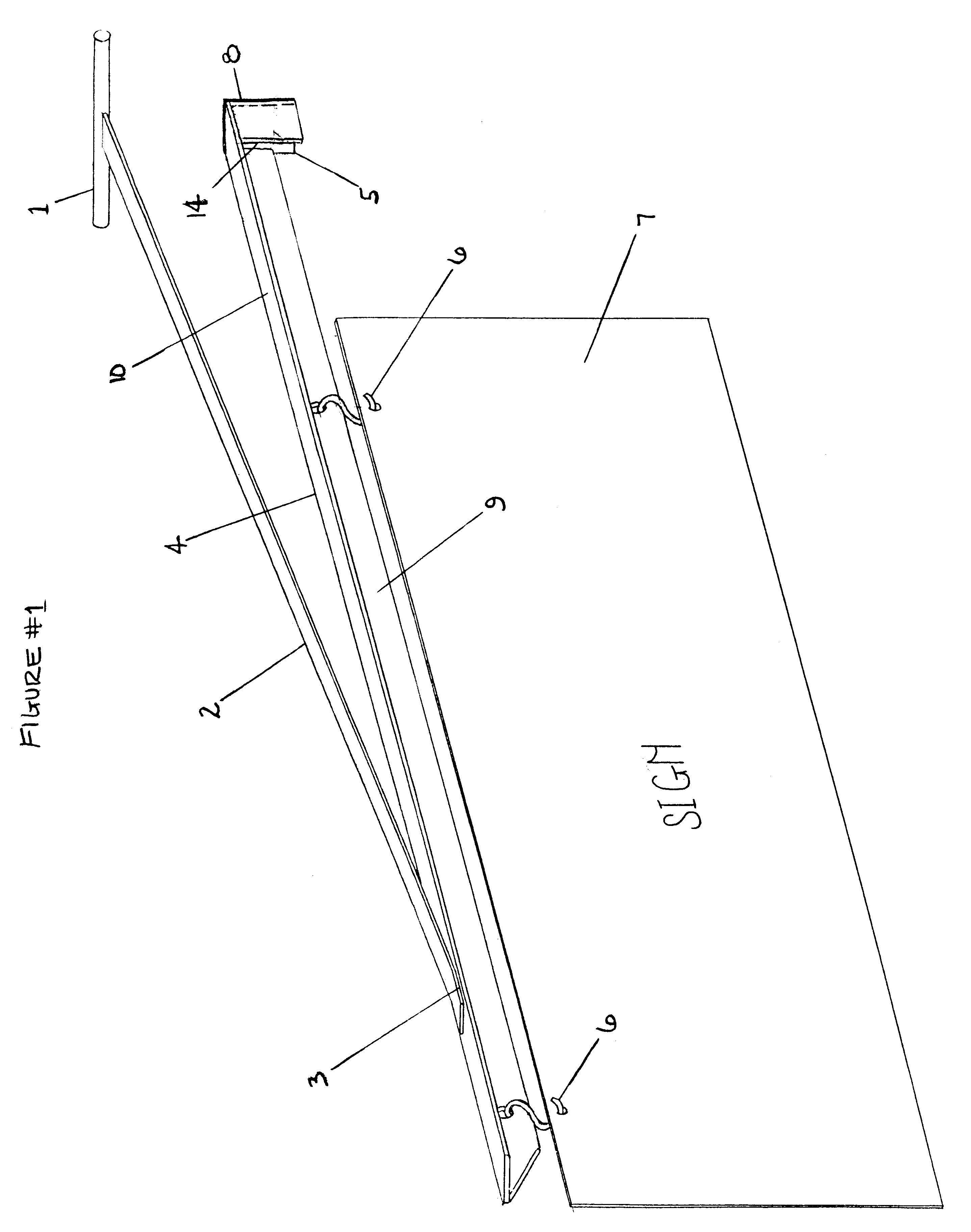
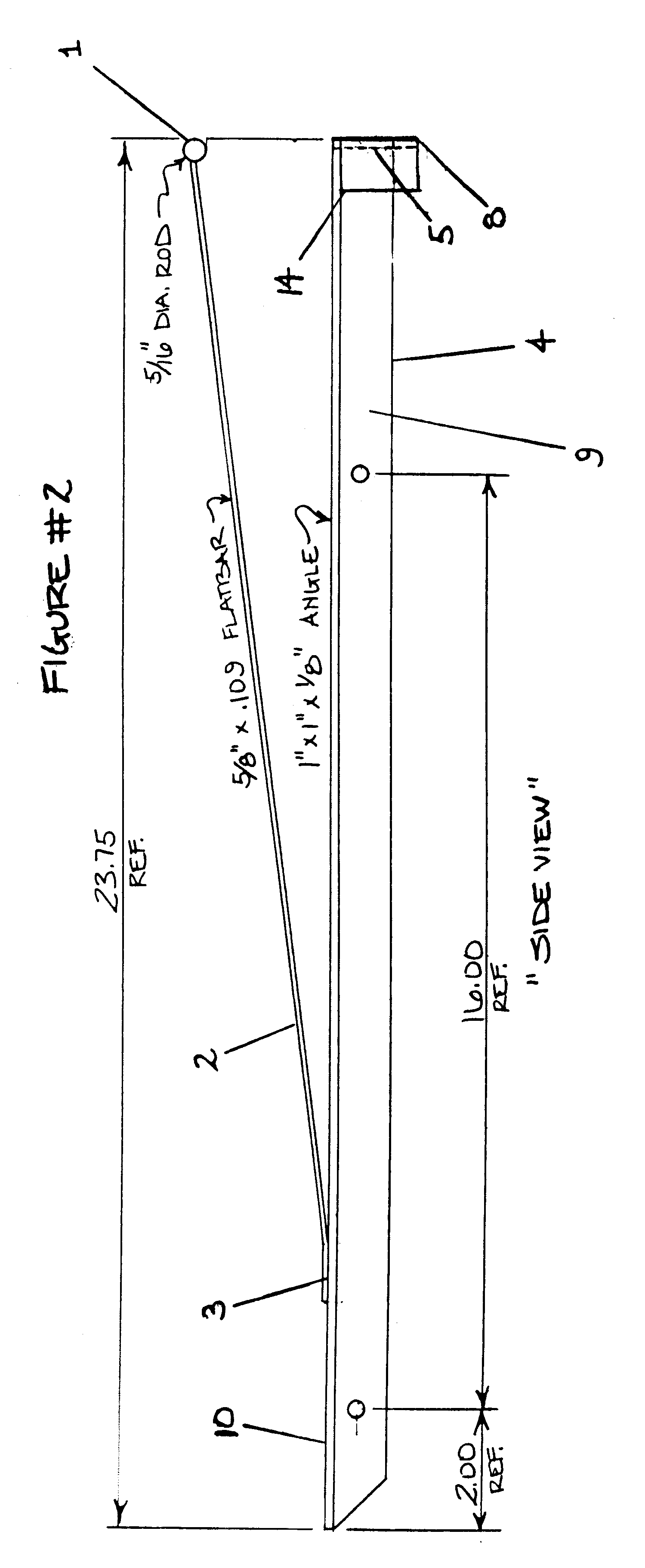
Operation of the device is simple and straightforward. In FIG. 1, the metal flatbar 2 is welded 3 to the top leg 10 of the metal angle iron 4. At the opposite end, a cylindrical metal dowel 1 is welded to the flatbar 2. This dowel 1 is then inserted into a cylindrical metal mounting rail. The inside downturn leg 9 has two predrilled holes in which "S" hooks are attached and act as natural load-bearing stress points. The end plate 5 has a square strip of adhesive foam pad 8 attached to prevent abrasion to the surface the device is resting against. The smaller outside rectangular downturn leg 14, attached to the end plate 5, provides additional support for the top leg 10 and end plate 5. It is slightly longer vertically than the inside downturn leg 9 and exactly the same vertical length as the end plate 5 and adhesive foam pad 8 attached to the end plate 5.

FIG. 2 demonstrates the functionality of the device by showing a sign 7 attached to the inside downturn leg 9 with "S" hooks 6.

FIG...


PUM


Abstract

A metal angle iron bar 4, with a flatbar 2 welded to the angle iron bar 4 at point 3 on the top leg 10. The flatbar 2 having a metal dowel 1 welded to the end opposite of point 3. A pad 8 is attached to the end of the angle iron bar 4 and two cylindrical holes are drilled in the downturn leg 9 of the angle iron bar 4 to accommodate two "S" hooks. The outside downturn leg 14 provides additional support and stress accommodation to the end plate 5 and top leg 10.

Description

BACKGROUND--FIELD OF INVENTIONThis invention is designed to support a hanging sign. It is affixed perpendicularly to the side of a recreational vehicle, or outside wall of a building or edifice, by way of a mounting rail. It will provide stable support from which the sign may be displayed.BACKGROUND--DESCRIPTION OF PRIOR ARTAttaching a horizontal sign to a vertical edifice is often cumbersome and difficult. It typically involves the application of a bulky bracket with many screws and anchoring supports to be affixed to the wall. The corresponding device, fitted to the bracket, is usually comprised of multiple parts which interlock and connect with the bracket at many different stress points to accommodate the weight to the sign. The use of multiple parts increases the likelihood of failure for one of the individual components and hence the degradation and eventual failure of the entire support mechanism. Additionally, the use of multiple parts make the assembly and installation proc...

Claims


Application Information

Patent Timeline
IPC IPC(8): G09F21/00G09F7/18G09F21/04G09F7/22
CPCG09F7/18G09F21/04G09F7/22G09F2007/186
Inventor COON, GARY T.
Owner COON GARY T
Why Eureka
Try Eureka