
Shielding method and apparatus for selective attenuation of an electromagnetic energy field component

a shielding method and electromagnetic energy field technology, applied in the field of well logging tools, can solve the problems of significant undesired em field components generation, and none of these disclosures address the implementation of antenna shields

Inactive Publication Date: 2002-02-26
SCHLUMBERGER TECH CORP
View PDF7 Cites 111 Cited by
  • Summary
  • Abstract
  • Description
  • Claims
  • Application Information

AI Technical Summary

Problems solved by technology

However, under actual operating conditions, there are various factors that give rise to the generation of significant undesired EM field components.
None of these disclosures address the implementation of antenna shields as alternative means to achieve selective EM energy attenuation.

Method used


Image

  • Shielding method and apparatus for selective attenuation of an electromagnetic energy field component
  • Shielding method and apparatus for selective attenuation of an electromagnetic energy field component
  • Shielding method and apparatus for selective attenuation of an electromagnetic energy field component

Examples


Embodiment Construction

In the interest of clarity, not all features of actual implementation are described in this specification. It will be appreciated that although the development of any such actual implementation might be complex and time-consuming, it would nevertheless be a routine undertaking for those of ordinary skill in the art having the benefit of this disclosure.

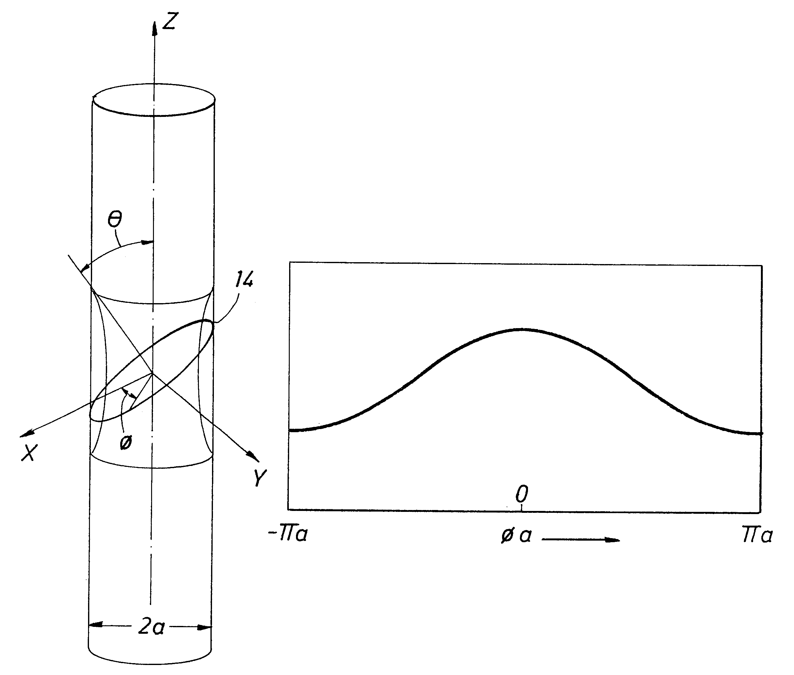
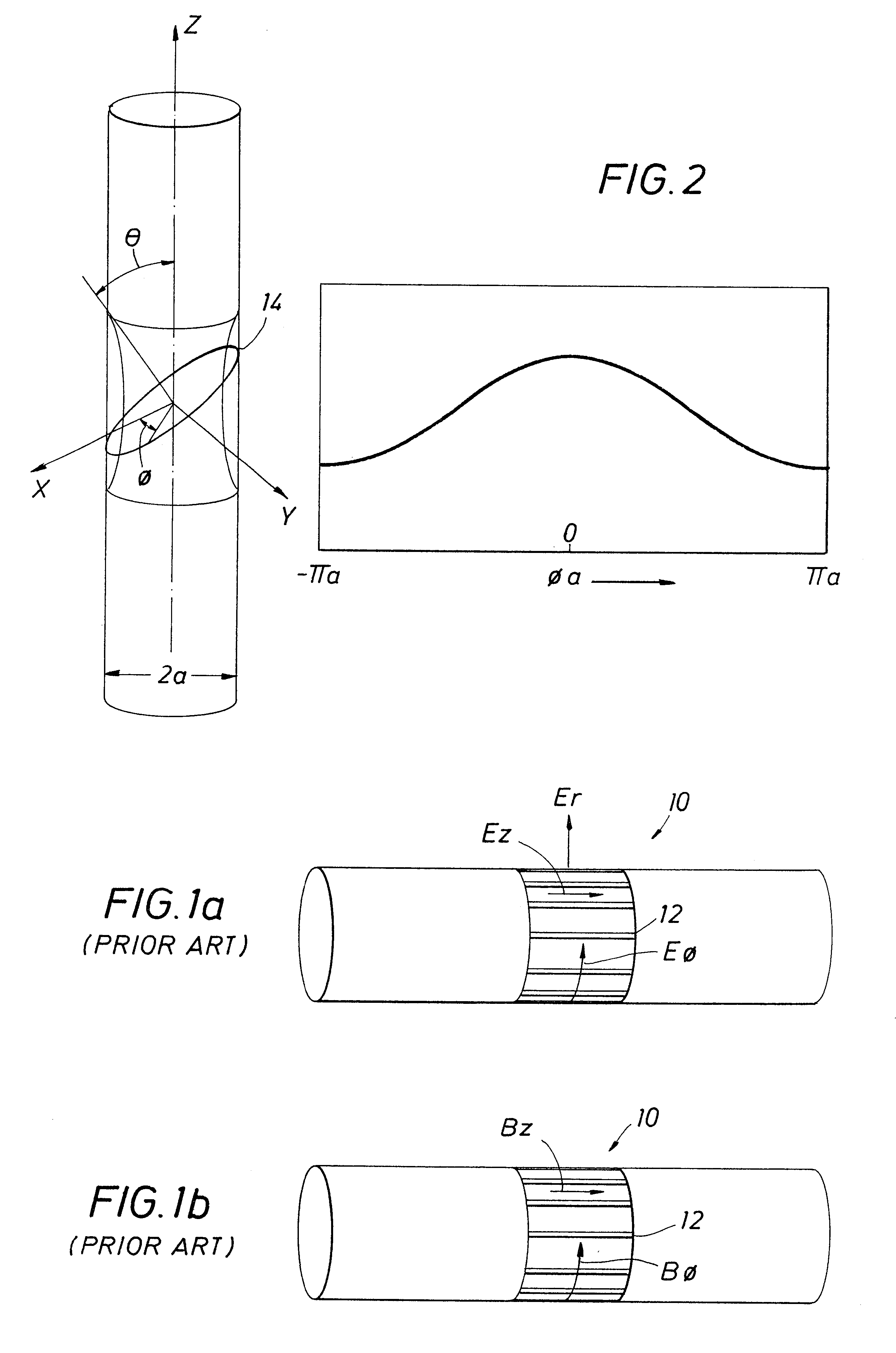
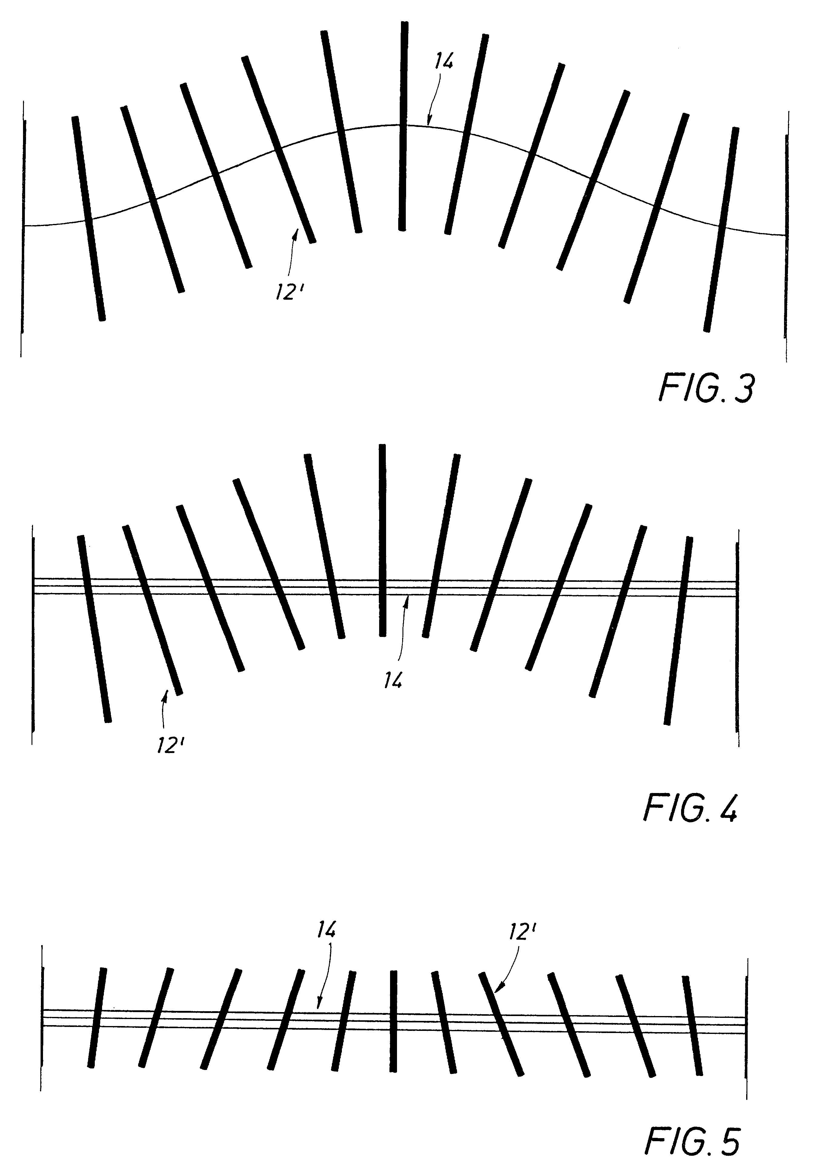
As discussed above, conventional shields used in well tools universally have slots that are aligned along the longitudinal axis of the tool. The orientation of the slots is perpendicular to the electric field generated by the coil within or the field that is to be detected by the receiver. If the incident field has an unwanted component of the electric field that lies along the slot, then currents will flow in the metal to cancel that field and only the normal component will remain. For conventional induction or propagation tools, the desired electric field is azimuthal, and longitudinal slots allow that field to pass. If the coil was...


PUM


Abstract

A shield apparatus for use in conjunction with a well tool to selectively attenuate one or more electromagnetic energy field components as the components interact with the shield. The shield composed of a flexible strip or conductive body and comprising at least one sloped slot or sloped conductive element therein. The shield being adapted to surround an antenna mounted on a well tool. A method for rotating the axis of the magnetic dipole of a transmitter or receiver coil. A method for winding and shielding an electric coil such that the resultant coil emits or receives selected electromagnetic energy field components.

Description

1.1 Field of the InventionThis invention relates to the field of well logging tools of the type wherein electromagnetic ("EM") energy is used for measuring characteristics of formations surrounding a borehole. More particularly, this invention relates to an improved antenna coil shield for use in such tools to provide selective attenuation of the EM waves emitted or received by the antenna.1.2 Description of Related ArtInduction and propagation well tools have been employed in logging operations for many years to measure the properties of subsurface formations surrounding an earth borehole. In conventional logging techniques, a number of antennae or coils are mounted on a well tool. An alternating current energizes one or more transmitter coils to emit EM energy into the formations. The emitted energy propagates through the formations or induces currents in the formations surrounding the borehole. The EM energy or currents are detected and measured by one or more receiver coils on t...

Claims


Application Information

Patent Timeline
Patent Type & Authority Patents(United States)
IPC IPC(8): G01V3/28G01V3/18
CPCG01V3/28
Inventor ROSTHAL, RICHARD A.HOMAN, DEAN M.OMERAGIC, DZEVATBONNER, STEPHEN D.CLARK, BRIANCHESSER, SCOTT S.BARBER, THOMAS D.
Owner SCHLUMBERGER TECH CORP
Learn More