Device for locking end positions of mobile switch parts

a technology for locking end positions and switch parts, which is applied in the direction of railway signalling, transportation and packaging, and ways, etc., can solve the problems of inadmissible deformation, and inability to move the rod

Inactive Publication Date: 2002-03-12
VAE AG
View PDF5 Cites 15 Cited by
  • Summary
  • Abstract
  • Description
  • Claims
  • Application Information

AI Technical Summary

Problems solved by technology

Since those locking forces can be taken up by balls only via a line point contact, the points of contact are exposed to an excessively high load, which may lead to inadmissible deformations.
In such cases, the tensile load exerted on the balls becoming active for actuation in that event would suffice to shift those balls together with their ring segments in

Method used


Image

  • Device for locking end positions of mobile switch parts
  • Device for locking end positions of mobile switch parts
  • Device for locking end positions of mobile switch parts

Examples


Embodiment Construction

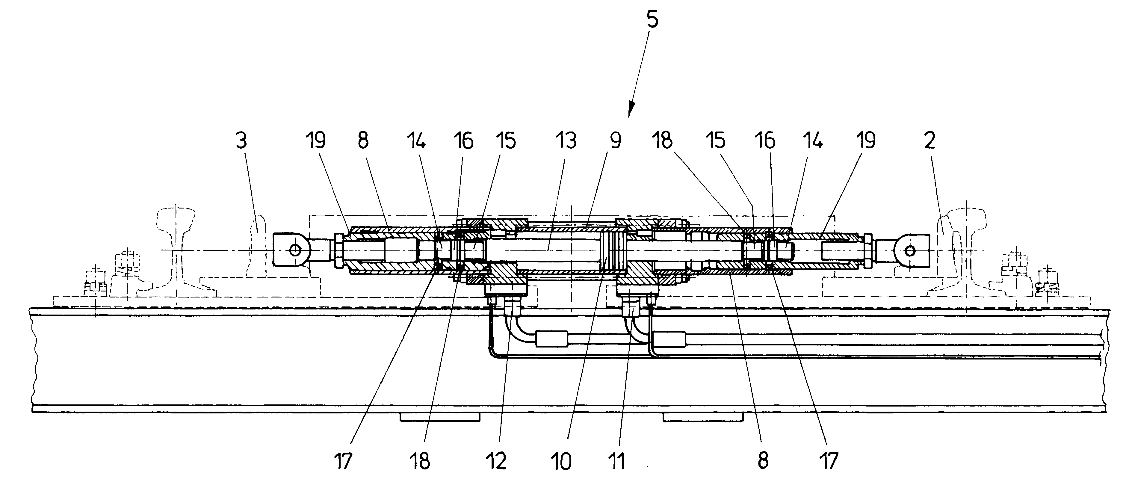
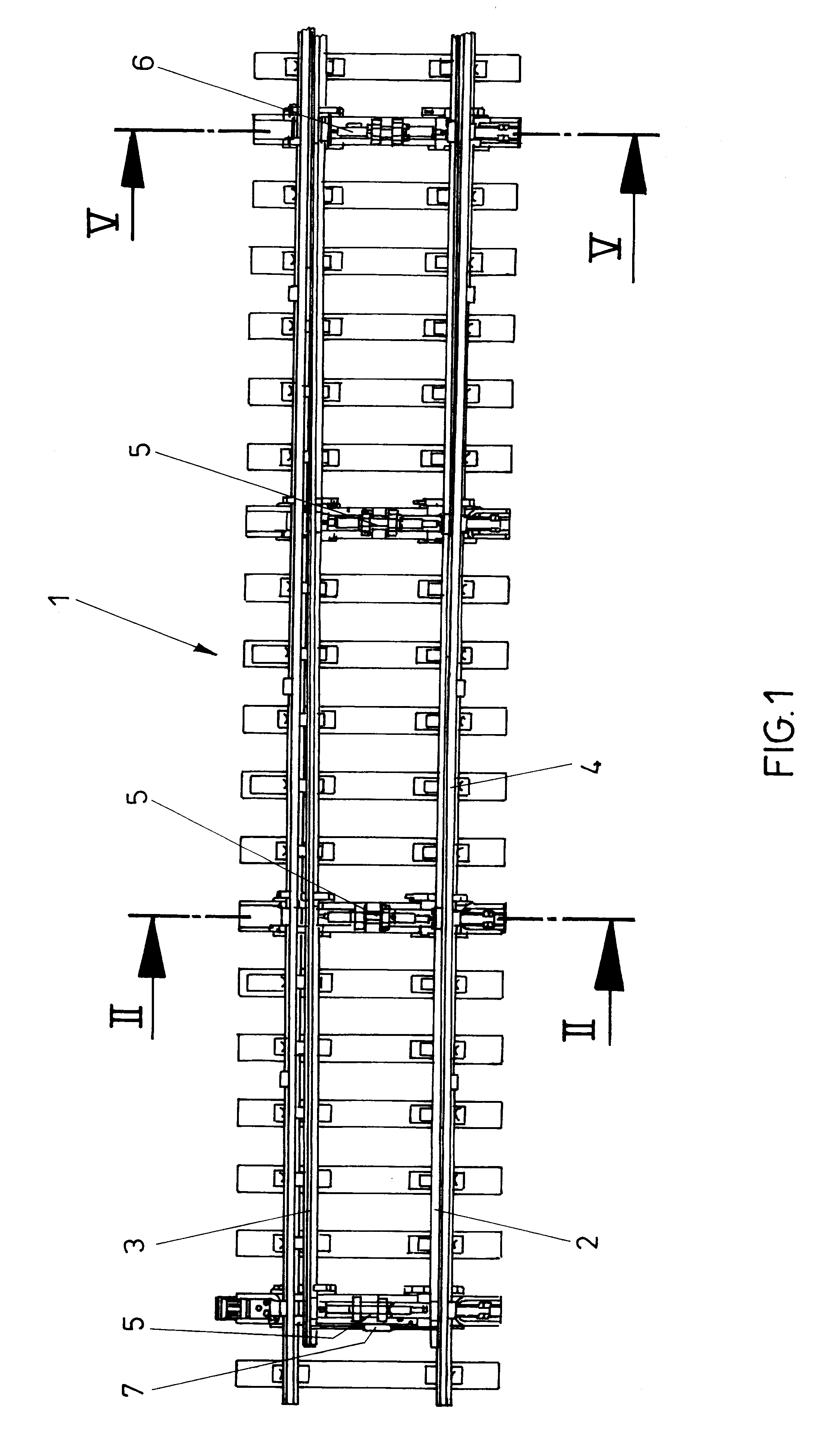
FIG. 1 depicts a railway switch 1 with switch tongues 2 and 3 being provided. The switch tongue 2 is in its closed position on the continuous rails 4, whereas the switch tongue 3 in the illustration according to FIG. 1 is in its open position. Between the switch tongues 2 and 3 are respectively provided devices for displacing and locking the positions of the switch tongues 2 and 3, which are denoted by 5. The first such unit that is remote from the tongue end is denoted by 6, since that unit differs from the other units in terms of structure.

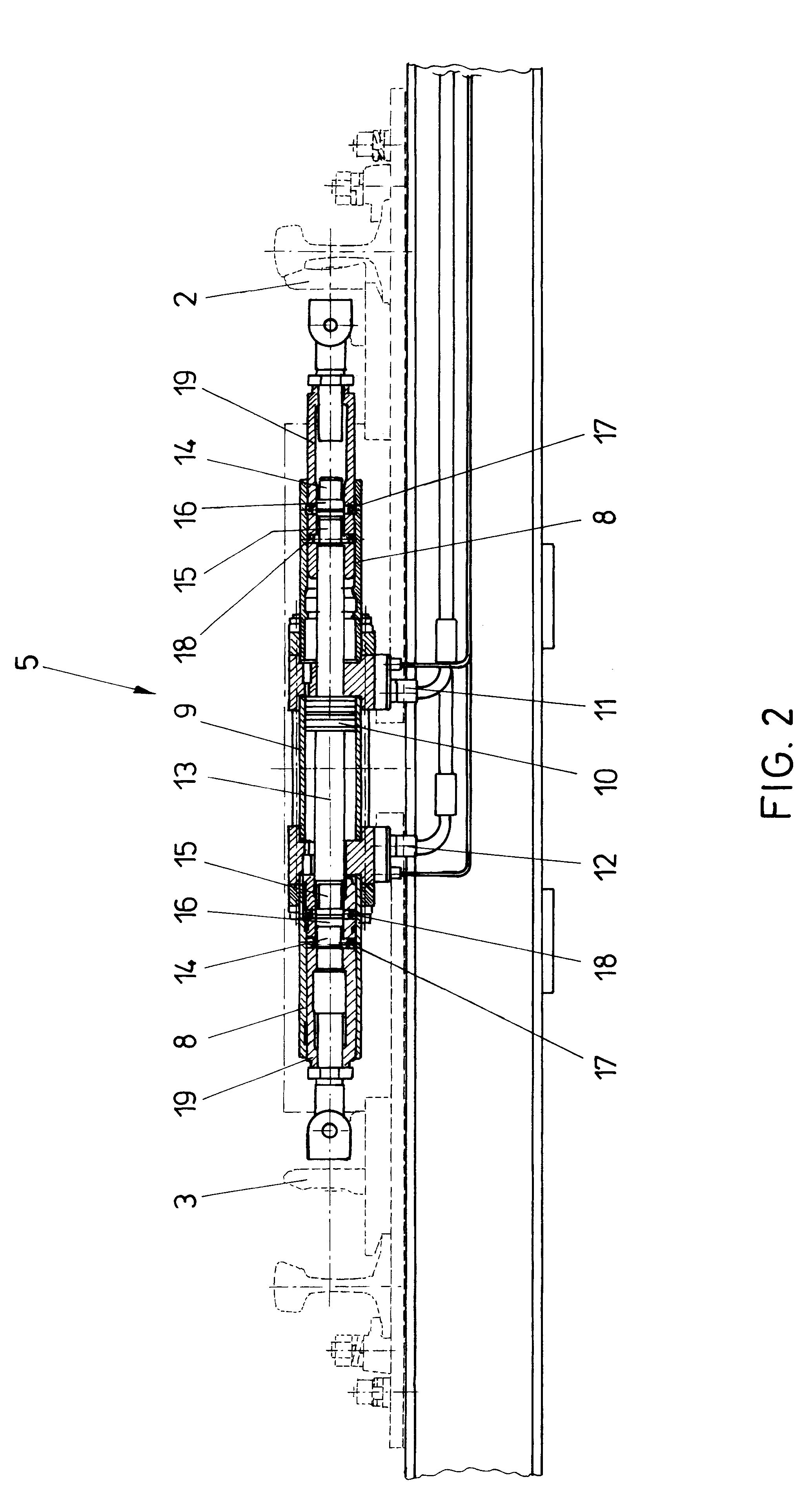
In the first device 5 adjacent the tongue ends, a coupling rod 7 is additionally visible, which during the displacement of one tongue safeguards the respectively corresponding movement of the second tongue in a positive and force-transmitting manner. The precise functions of the individual devices 5 and 6, respectively, are elucidated in the following detailed drawings. FIG. 2 depicts a device for locking the end positions of switch tongues, whi...


PUM


Abstract

A device for locking the end positions of movable railway switch parts in which two parts axially displaceable relative to each other are displaced into a position coupled to each other for movement in at least one direction. The relatively displaceable parts, formed by a tube and a rod guided within the tube, are arranged at least partially within a stationary external tube. Locking elements comprising balls cooperate with the axially displaceable parts and the external tube and are displaceable radially into a lock position within a recess of the external tube. The balls are surrounded by a ring resiliently held in a position having an outer diameter smaller than, or equal to, the outer diameter of the axially displaceable tube retained in a peripheral groove of the tube. The balls are arranged in openings in the tube between the rod and the ring.

Description

1. Field of the InventionThe invention relates to a device for locking the end positions of movable railway switch parts, in particular a switch lock, in which two parts capable of being axially displaced relative to each other are displaceable into a position coupled to each other in a positive and force-transmitting manner in at least one moving direction, wherein the relatively displaceable parts are formed by a tube and a rod guided within the tube and are arranged at least partially in a stationary external tube, wherein locking elements comprised of balls cooperate with the axially displaceable parts and the external tube and are displaceable in the radial direction into a lock position into a recess or internal ring groove of the external tube.2. Prior ArtA device of the above-mentioned kind has already become known from EP-A 603 156, in which locking elements comprised of balls are pressed into their lock positions by means of stops comprised of thickened rod regions, said l...

Claims


Application Information

Patent Timeline
IPC IPC(8): B61L5/00B61L5/10
CPCB61L5/10
Inventor ACHLEITNER, HERBERTHORTLER, JOSEF
Owner VAE AG
Why Eureka
Try Eureka