Adjustable fit progressive cavity pump/motor apparatus and method

a progressive cavity, pump technology, applied in machines/engines, liquid fuel engines, borehole/well accessories, etc., can solve the problems of elastomeric member wear, rotor and stator interference is especially prone to deterioration, and the predetermined amount of interference is difficult at best to obtain for efficient performan

Inactive Publication Date: 2002-03-19
WEATHERFORDLAMB
View PDF20 Cites 54 Cited by
  • Summary
  • Abstract
  • Description
  • Claims
  • Application Information

AI Technical Summary

Problems solved by technology

The rubbing of the rotor in the stator as the rotor rotates causes several problems.
Various operating conditions change the interference fit and therefore a predetermined amount of interference is difficult at best to obtain for efficient performance under the varying conditions.
For example, the rubbing causes the elastomeric member to wear.
Further, the interference fit between the rotor and stator is especially prone to deterioration from particulates in a production fluid.
Still further, the rubbing itself produces heat buildup in the elastomeric member and decreases the life of the elastomeric member.
The temperature fluctuations can cause the components, particularly the elastomeric member, to swell and change the interference fit between the stator and rotor.
Further, swelling can occur with time of use and with chemicals existing in production fluids.
The swelling can be great enough to damage the pump and require repair or replacement.
However, the reference does not address adjustments needed to solve the problems of swelling or deterioration or the varying operating conditions.

Method used


Image

  • Adjustable fit progressive cavity pump/motor apparatus and method
  • Adjustable fit progressive cavity pump/motor apparatus and method
  • Adjustable fit progressive cavity pump/motor apparatus and method

Examples


Embodiment Construction

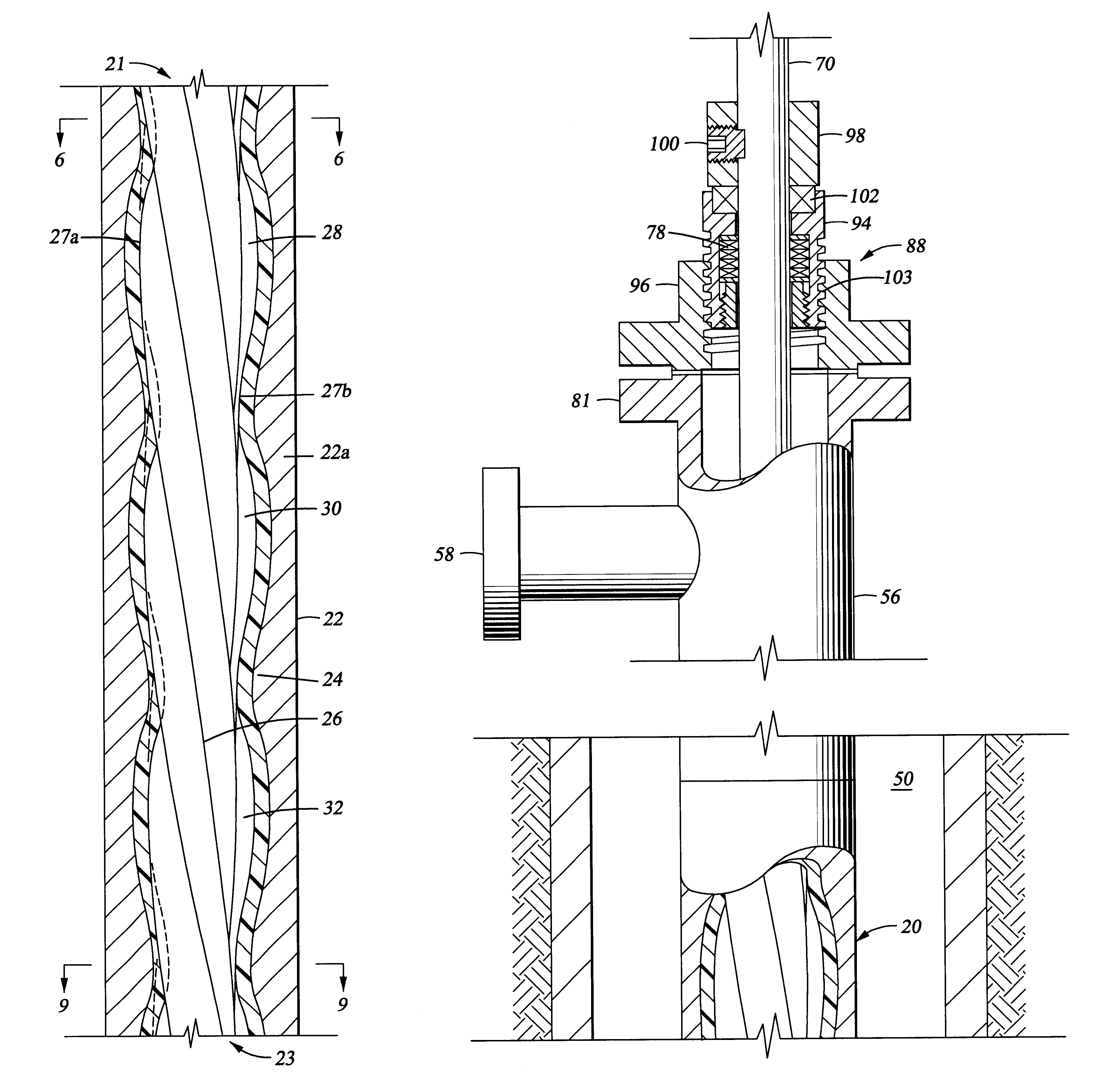
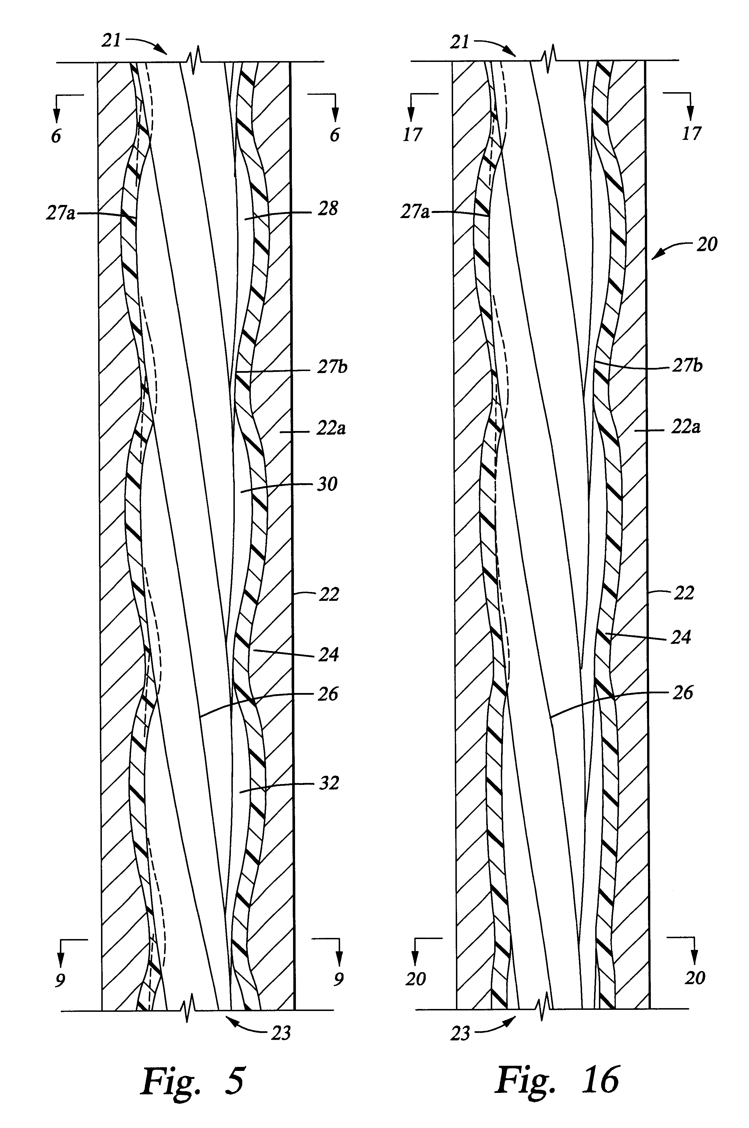
FIG. 5 is a schematic cross sectional view of a portion of a PCP. The PCP 20 has a rotor and / or stator with a tapered cross section. In one embodiment, the rotor is tapered progressively smaller at a minor diameter of the rotor from a first portion 21 to a second portion 23 of the PCP 20. Similarly, the stator could be tapered progressively smaller from the first portion 21 to the second portion 23 to correspond to the rotor. Alternatively, the tapers can be progressively larger from the first portion to the second portion. Generally, in some embodiments, the fit / clearance between the rotor and the stator is relatively constant if the tapers on the rotor and stator are uniform. If other embodiments, the fit / clearance itself can be tapered if the tapers of the rotor and stator are nonuniform.

The PCP 20 includes a stator 22, having a shell 22a and a elastomeric member 24 generally coupled to the shell 22a, and a rotor 26 disposed therethrough. Generally, the shell 22a and the rotor ar...


PUM


Abstract

The present invention provides an adjustable rotor and/or stator, so that the interference fit and/or clearance can be adjusted. The rotor and/or stator are tapered to provide a difference in fit between the rotor and stator by longitudinal adjustment of their relative position. In one embodiment, the adjustment may occur while the PCP in mounted downhole in a wellbore. In another embodiment, the adjustment may occur automatically depending on sensor input of operating conditions of the PCP.

Description

1. Field of the InventionThe present invention relates to the equipment and methods in oil field operations. Particularly, the invention relates to helical gear pumps.2. Background of the Related ArtHelical gear pumps, typically known as progressive cavity pumps / motors (herein PCPs), are frequently used in oil field applications, for pumping fluids or driving downhole equipment in the wellbore. A typical PCP is designed according to the basics of a gear mechanism patented by Moineau in U.S. Pat. No. 1,892,217, incorporated by reference herein, and is generically known as a "Moineau" pump or motor. The mechanism has two helical gear members, where typically an inner gear member rotates within a stationary outer gear member. In some mechanisms, the outer gear member rotates while the inner gear member is stationary and in other mechanisms, the gear members counter rotate relative to each other. Typically, the outer gear member has one helical thread more than the inner gear member. Th...

Claims


Application Information

Patent Timeline
Patent Type & Authority Patents(United States)
IPC IPC(8): F04C2/107F04C2/00
CPCF04C2/1071F04C2250/201E21B43/126E21B4/02
Inventor LANE, WILLIAM
Owner WEATHERFORDLAMB
Why Eureka
Try Eureka