Locking device

a technology of locking device and locking element, which is applied in the direction of cylinder locks, non-mechanical controls, lock applications, etc., can solve the problems of inability to operate reliably, the locking device could be undetectable by external influences, and the risk of restoring force on the inhibiting element is inherent. , to achieve the effect of reliable operation

Inactive Publication Date: 2002-04-02
KABA SCHLIESSYST
View PDF24 Cites 65 Cited by
  • Summary
  • Abstract
  • Description
  • Claims
  • Application Information

AI Technical Summary

Benefits of technology

An object of the invention is to provide a mechanical-electronic locking device which is resistant to external influences, particularly vibration and / or shock effects or magnetic actions, and which ensures reliable operation.
However, an additional risk is inherent in exerting a restoring force on the inhibiting element. As is known, a mobile mass on which a restoring force acts forms an oscillator with at least one resonant frequency. Such an oscillator can be resonantly vibrated by excitation with a suitable frequency and the amplitude of these vibrations, as a function of the damping present, can be very considerable. Under this effect, the locking device could be undesirably opened by external influences.
In order to prevent this, freely vibrating masses are avoided to the greatest possible extent in the locking device and method according to the invention. For this purpose, the position of the inhibiting element is clearly predetermined by suitable guidance means which prevents resonant vibrations of the mass of the inhibiting element.

Problems solved by technology

Such mechanisms can result from asymmetric damping, feedback of other oscillating or vibrating elements, etc.
However, an additional risk is inherent in exerting a restoring force on the inhibiting element.
Under this effect, the locking device could be undesirably opened by external influences.

Method used


Image

  • Locking device
  • Locking device
  • Locking device

Examples


Embodiment Construction

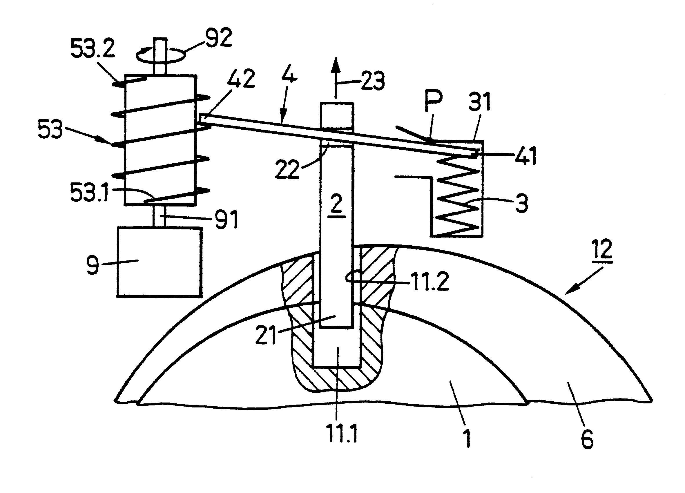
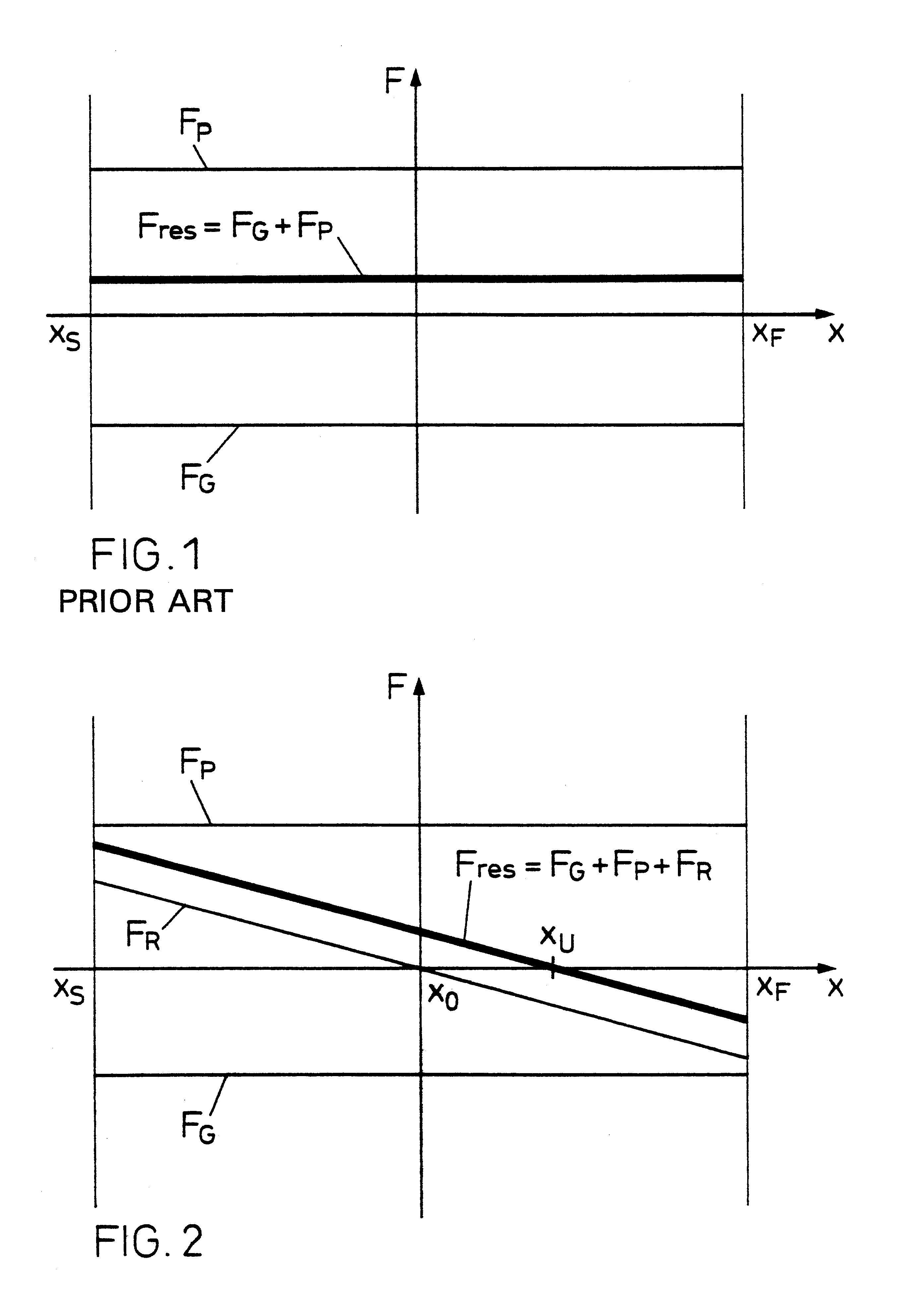
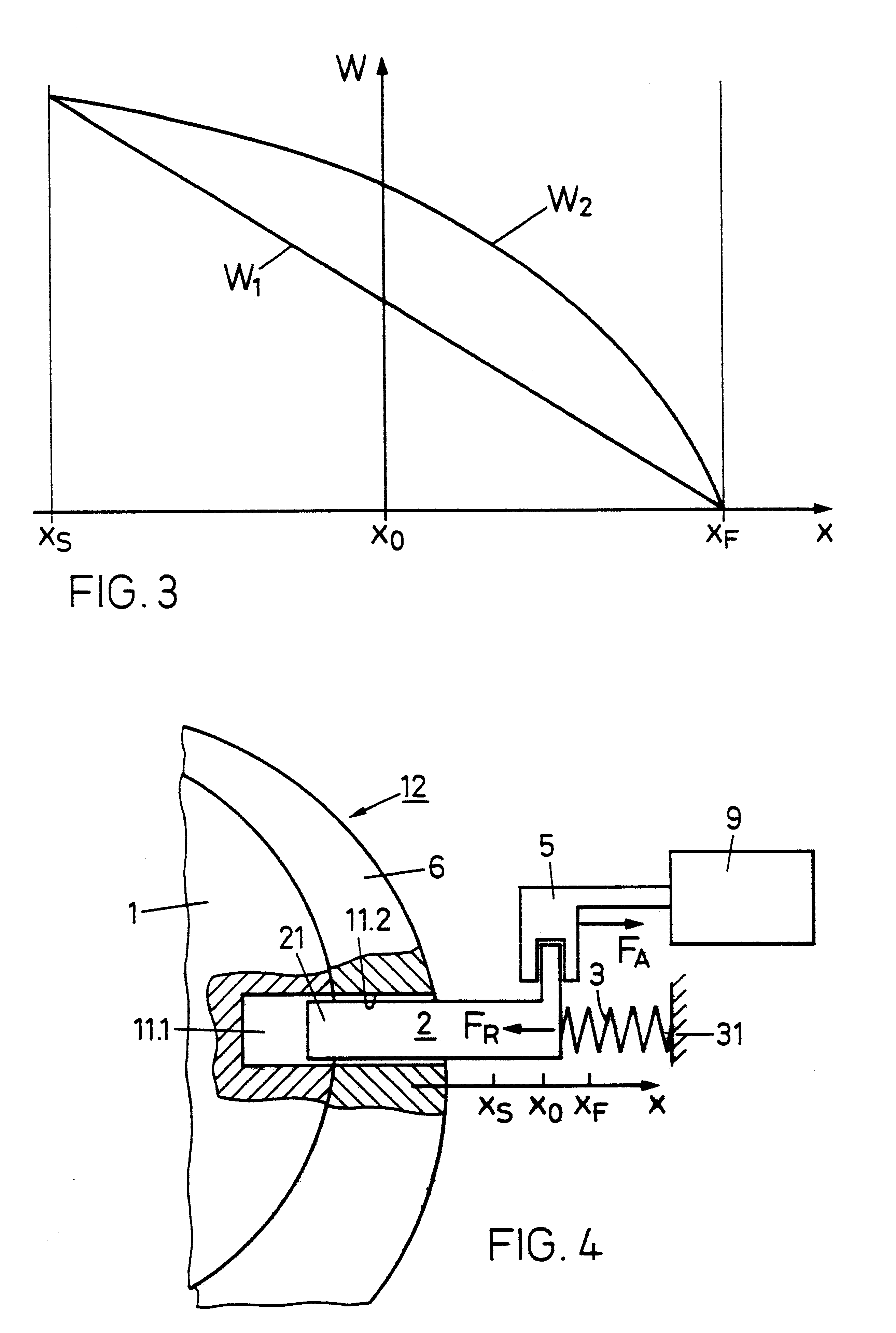
In each of FIGS. 1 and 2 are plotted forces F(x) on an inhibiting or blocking element as a function of a space coordinate x along which the inhibiting element can move and in which:

x.sub.S is an inhibit position, i.e., the position to be occupied by the inhibiting element when it blocks or inhibits movement of the lock cylinder, i.e., the rotor and stator are mutually locked;

x.sub.F is a release or free position, i.e., the position to be occupied by the inhibiting element in which it releases or frees the lock cylinder for movement to the stator;

x.sub.O is a rest position, i.e., the inhibiting element position in which, in the locking device according to the invention, no restoring force acts on the inhibiting element.

The inhibiting element must only release the lock cylinder in the free position x=x.sub.F, whereas it must inhibit the same in positions x0act in the positive x-direction and negative forces F<0, in the negative x-direction.

FIG. 1 is a force / distance diagram for a prio...


PUM


Abstract

A locking device for a lock cylinder (12) has an electronically controlled inhibiting element (2), which in an inhibit position (x.sub.S) blocks movement of a rotor (1) relative to a stator (6) and frees the rotor (1) in a free position (x.sub.F). A drive (9) exerts a working force (F.sub.A) on the inhibiting element (2), by which inhibiting element (2) can be reversibly transferred from the inhibit position (x.sub.S) into the free position (x.sub.F) and vice versa. A guide (52-57) is connected to the drive (9) and, at least outside the free position (x.sub.F), clearly defines the position of the inhibiting element (2). A restoring device (3) exerts a restoring force (F.sub.R) directed away from the free position (x.sub.F) on the inhibiting element (2), when that element is between the free position (x.sub.F) and a rest position (x.sub.O). In the rest position (x.sub.O) and in positions between the rest position (x.sub.O) and the free position (x.sub.F), the inhibiting element inhibits movement of the rotor (1). The locking device is resistant to external, undesired vibration and / or shock effects or magnetic action.

Description

FIELD OF THE INVENTIONThis invention relates to a locking device usable in locking systems in buildings, vehicles, furniture, safes, switchgear cabinets, key-operated switches, etc. The invention also relates to a method for preventing the opening of a locking device.BACKGROUND OF THE INVENTIONLocking devices with mechanically and electronically controlled blocking or inhibiting elements are known. They have all the properties of conventional, purely mechanical locking devices. The additional, electronically controlled locking system also provides the possibility of individually activating and inhibiting keys. Thus, such mechanical-electronic locking devices lead to additional flexibility in the locking organization.Electronically controlled locking is based on data transmission between a key-side electronic module and a lock-side electronic module. This data transmission can take place by contact, e.g., by electrical contacts on the key and lock, or without contact, e.g., by electr...

Claims


Application Information

Patent Timeline
Patent Type & Authority Patents(United States)
IPC IPC(8): E05B47/06E05B47/00E05B27/00E05B49/02
CPCE05B47/063E05B47/0012E05B2047/0015E05B2047/0092E05B2047/0023E05B2047/0025E05B2047/0026E05B2047/002Y10T70/7136Y10T70/7102Y10T70/7079Y10T70/7096E05B47/06
Inventor KUENG, OTTO
Owner KABA SCHLIESSYST
Why Eureka
Try Eureka