Radial active magnetic bearing apparatus and a method for operating the same

a technology of active magnetic bearing and radial bearing, which is applied in the direction of bearings, electrical devices, dynamo-electric machines, etc., can solve the problems of complex processing, high cost per se, and three separate power amplifiers, which are specifically matched and therefore relatively expensiv

Inactive Publication Date: 2002-04-02
LUST ANTRIEBSTECHN
View PDF8 Cites 42 Cited by
  • Summary
  • Abstract
  • Description
  • Claims
  • Application Information

AI Technical Summary

Problems solved by technology

A disadvantage of this known magnetic bearing is to be seen in the fact that three separate power amplifiers are required, which are in addition specifically matched and are therefore relatively expensive.
Thus, the signal processing, which is complicated and expensive per se, can largely be carried out by the micro-controller integrated into the rotary current controller, which saves on the costs for an additional signal processing apparatus.

Method used


Image

  • Radial active magnetic bearing apparatus and a method for operating the same
  • Radial active magnetic bearing apparatus and a method for operating the same
  • Radial active magnetic bearing apparatus and a method for operating the same

Examples


Embodiment Construction

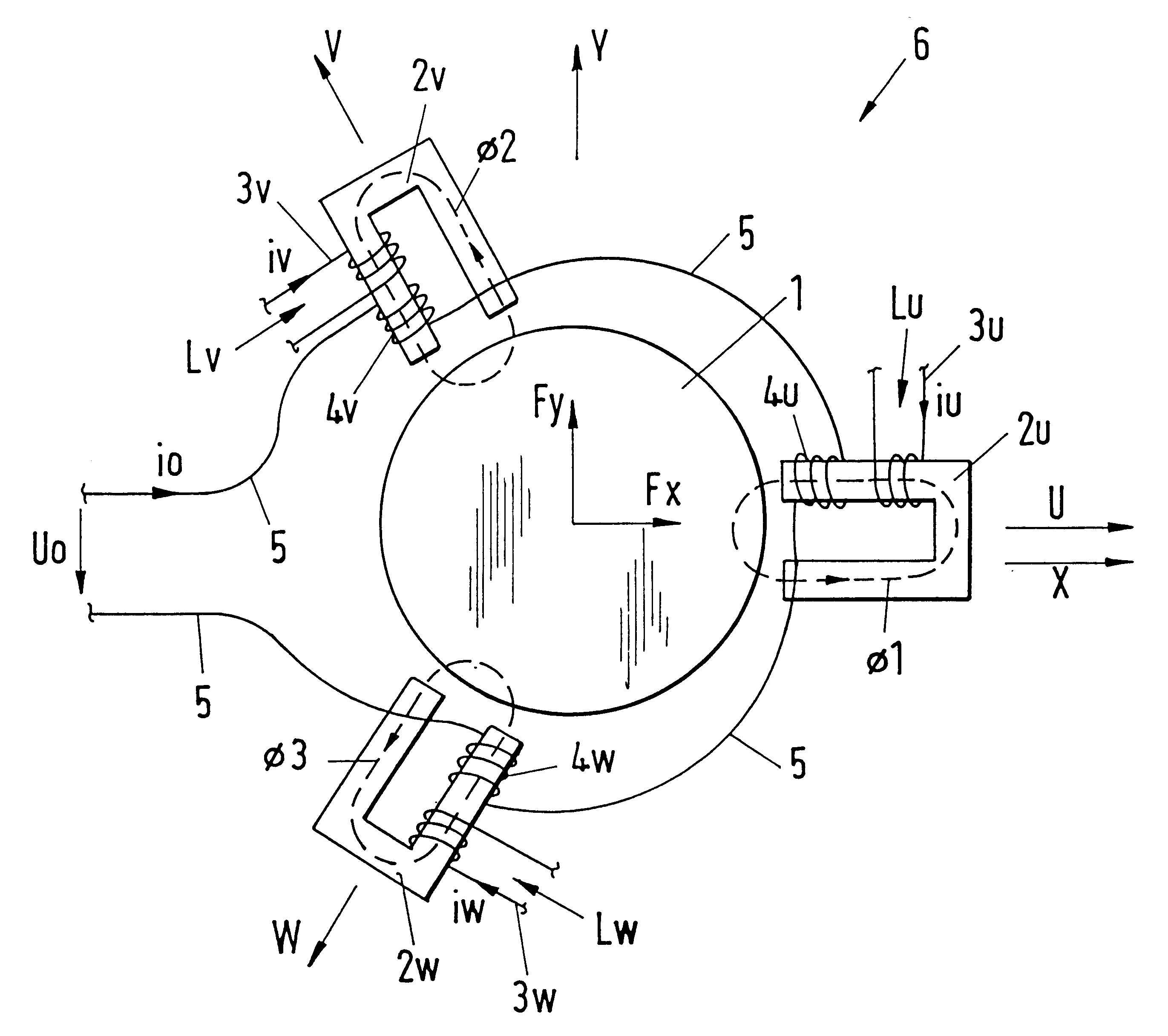
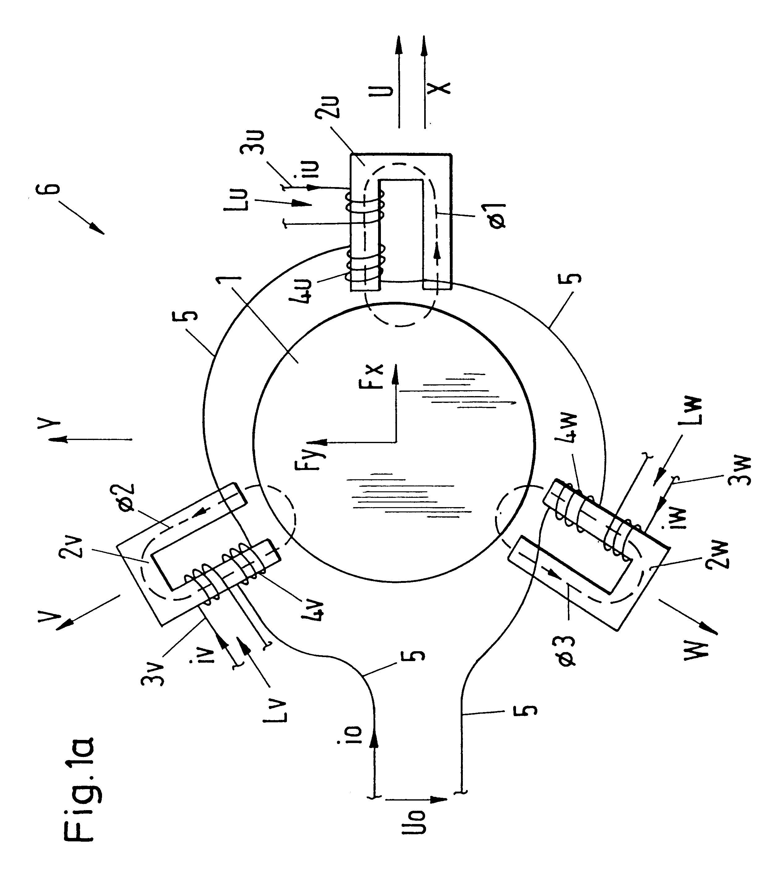
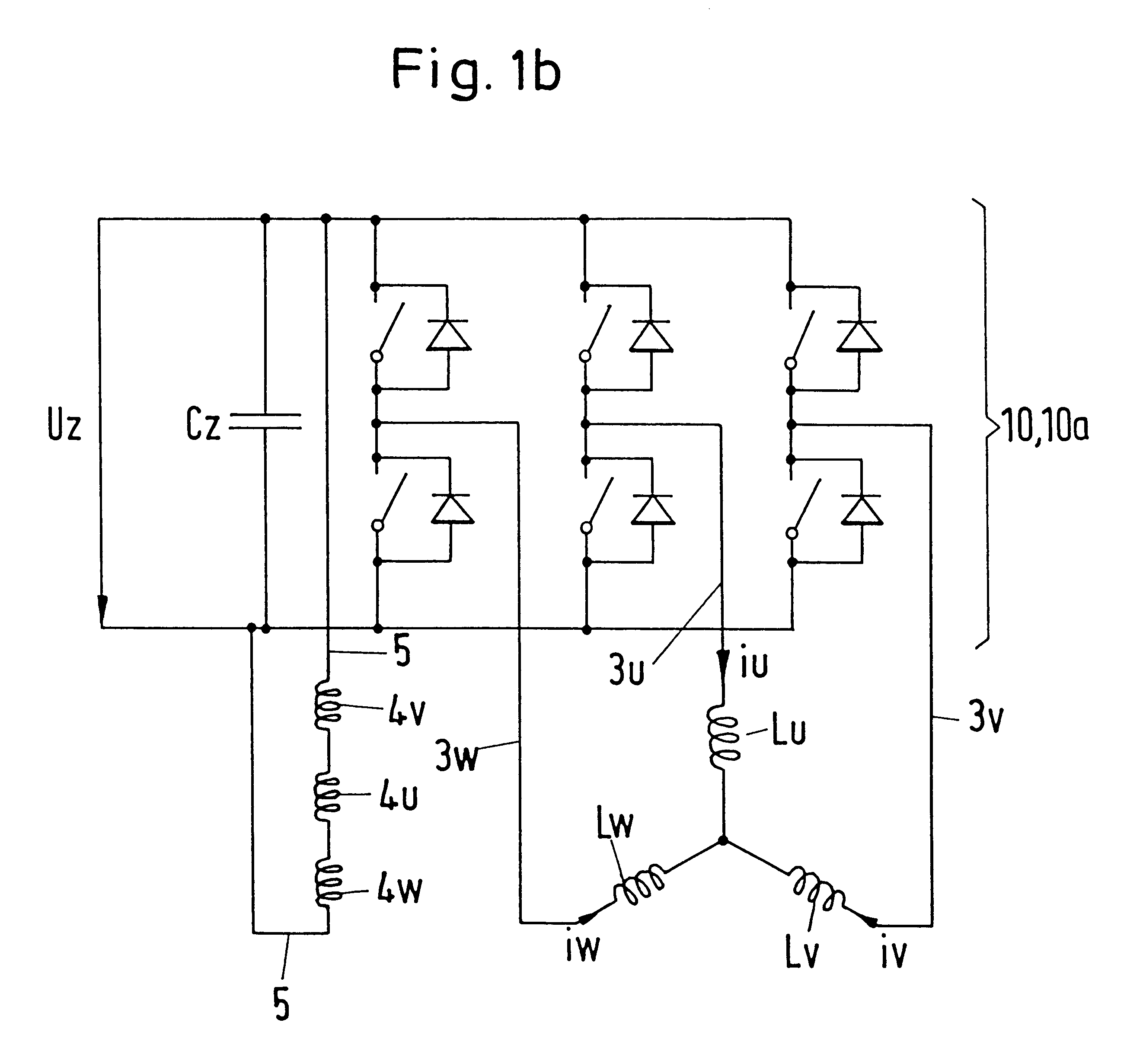
FIG. 1a shows a side view of an exemplary embodiment of a radial, active magnetic bearing. The rotor 1, which is designed as a shaft, is held in suspension without contact by three electromagnets 2u, 2v, 2w which are designed to be discrete and u-shaped and are respectively mutually displaced by 120.degree. in the peripheral direction in each case. Each electromagnet 2u, 2v, 2w has a coil Lu, Lv, Lw for the production of a magnetic flux .phi.1, .phi.2, .phi.3 which is variable in time. Each coil Lu, Lv, Lw is connected to a non-illustrated rotary current source 10 via electrical conduction lines 3u, 3v, 3w. The magnetic bearing requires a bias magnetization, which in the present exemplary embodiment is produced by three coils 4u, 4v, 4w through which a direct current flows. At each coil core 2u, 2v, 2w there is provided a coil 4u, 4v, 4w which is wound in the same direction. The coils 4u, 4v, 4w are connected to one another in a series circuit via an electrical conductor 5 and are t...


PUM


Abstract

A radial, active magnetic bearing apparatus comprising at least three electromagnets which are distributedly arranged is excited by a three-phase rotary current controller.

Description

1. Field of the InventionThe invention relates to a radial, active magnetic bearing apparatus comprising at least three electromagnets that are distributedly arranged in the bearing wherein a rotary current controller is provided for the excitation of the coils of the electromagnets.2. Description of the Prior ArtA radial, active magnetic bearing for the contact-free journalling of a rotatable body is known from EP 0 612 928. A magnetic bearing of this kind comprises in each case three electromagnets respectively mutually displaced by 120.degree. in the circumferential direction, with each of the three electromagnets being supplied with electrical energy by a separate amplifier. A disadvantage of this known magnetic bearing is to be seen in the fact that three separate power amplifiers are required, which are in addition specifically matched and are therefore relatively expensive.The object of the present invention is to provide an economically more advantageous, active magnetic bea...

Claims


Application Information

Patent Timeline
Patent Type & Authority Patents(United States)
IPC IPC(8): F16C39/06F16C39/00H02K7/09
CPCF16C32/0463F16C32/0476F16C32/0457F16C32/0487H02K7/09F16C32/048
Inventor SCHOB, RETO
Owner LUST ANTRIEBSTECHN
Why Eureka
Try Eureka