Mobile radio communication system

a radio communication system and mobile technology, applied in the field of mobile radio communication system, can solve the problems becoming difficult for the mobile station to select a beam from the base station, and requiring both the omnidirectional channel and the narrow beam channel to start a speech, so as to achieve the effect of reducing the tracking tim

Inactive Publication Date: 2002-04-09
MITSUBISHI ELECTRIC CORP
View PDF7 Cites 49 Cited by
  • Summary
  • Abstract
  • Description
  • Claims
  • Application Information

AI Technical Summary

Benefits of technology

is to solve the above problems, and to provide a mobile radio communication system which does not need an omnidirectional channel for both a base station and a mobile station to track each other and uses only a narrow beam channel. Another object of the present invention is to provide a mobile radio communication system which reduces a tracking time than before for an adjacent base station and a mobile station to search each other while a visiting base station and the mobile station are communicating in the overlapped area.

Problems solved by technology

But, when the mobile station approaches to a boundary between the base station 1102 and an adjacent base station, there is a problem in that it is becoming difficult for the mobile station to select a beam from the base station because of a interference wave coming from a plurality of the adjacent base stations.
As mentioned above, in conventional mobile radio communication system, when the mobile station approaches to a boundary between the base station and an adjacent base station, there is a problem in that it is becoming difficult for the mobile station to select a beam from the base station because of a interference wave coming from a plurality of the adjacent base stations.
In another conventional mobile radio communication system, there is a problem in that both of the omnidirectional channel and the narrow beam channel are needed to start a speech.
In the overlapped area, there is a problem in that the adjacent base station and the mobile station set the tracking channels of different frequency and different beam to avoid the interference and track each other, resulting in increasing tracking time.

Method used


Image

  • Mobile radio communication system
  • Mobile radio communication system
  • Mobile radio communication system

Examples


embodiment 1

described above, after both tracking between the mobile station 101 and the visiting area base station 102 has completed, switching to an information channel is performed using the same frequency and beam which are used by a tracking channel, thereby an operation switching a tracking channel to an information channel by another frequency and beam is not needed. Thus, a configuration of a device becomes more simple than a conventional system.

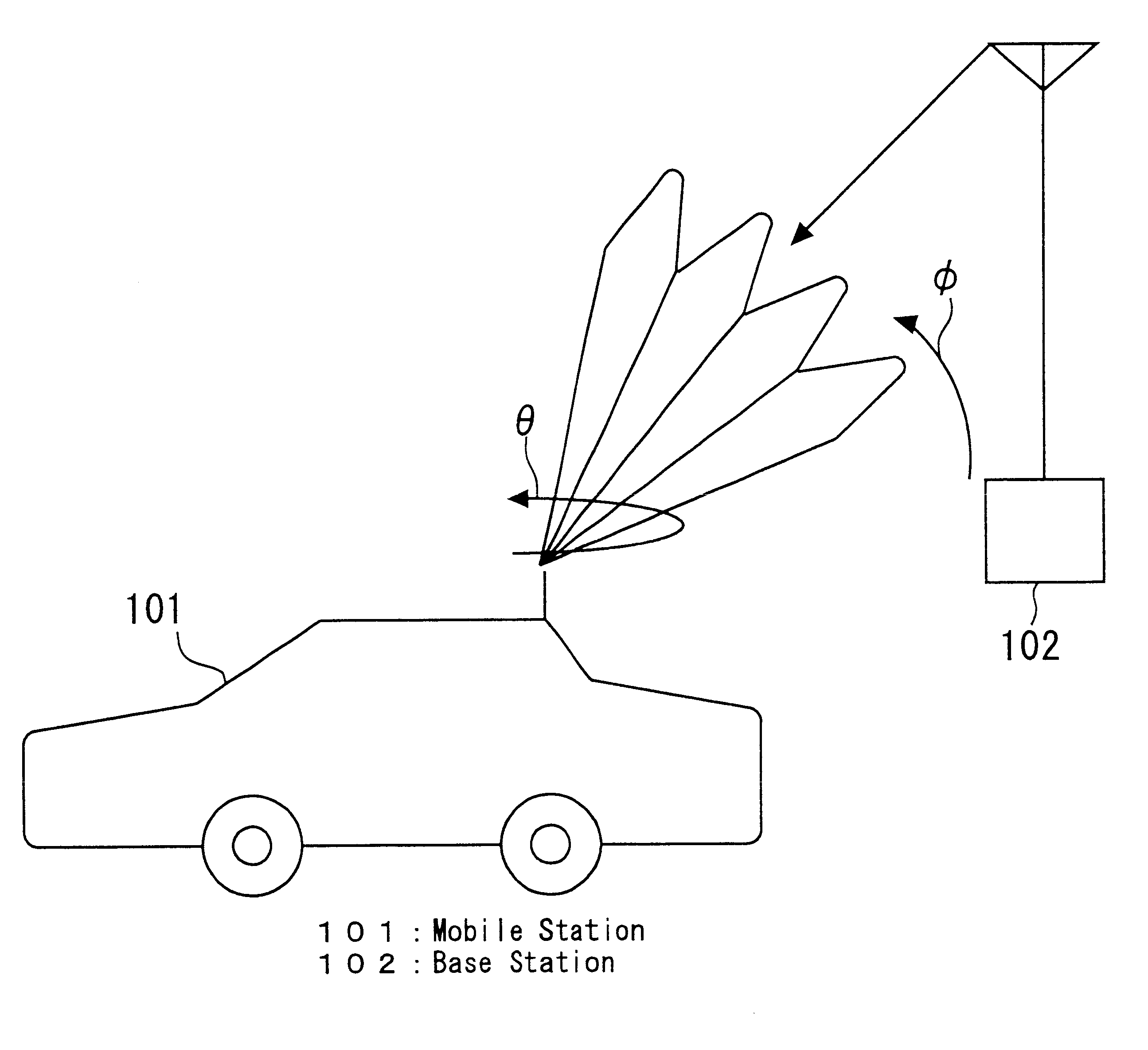
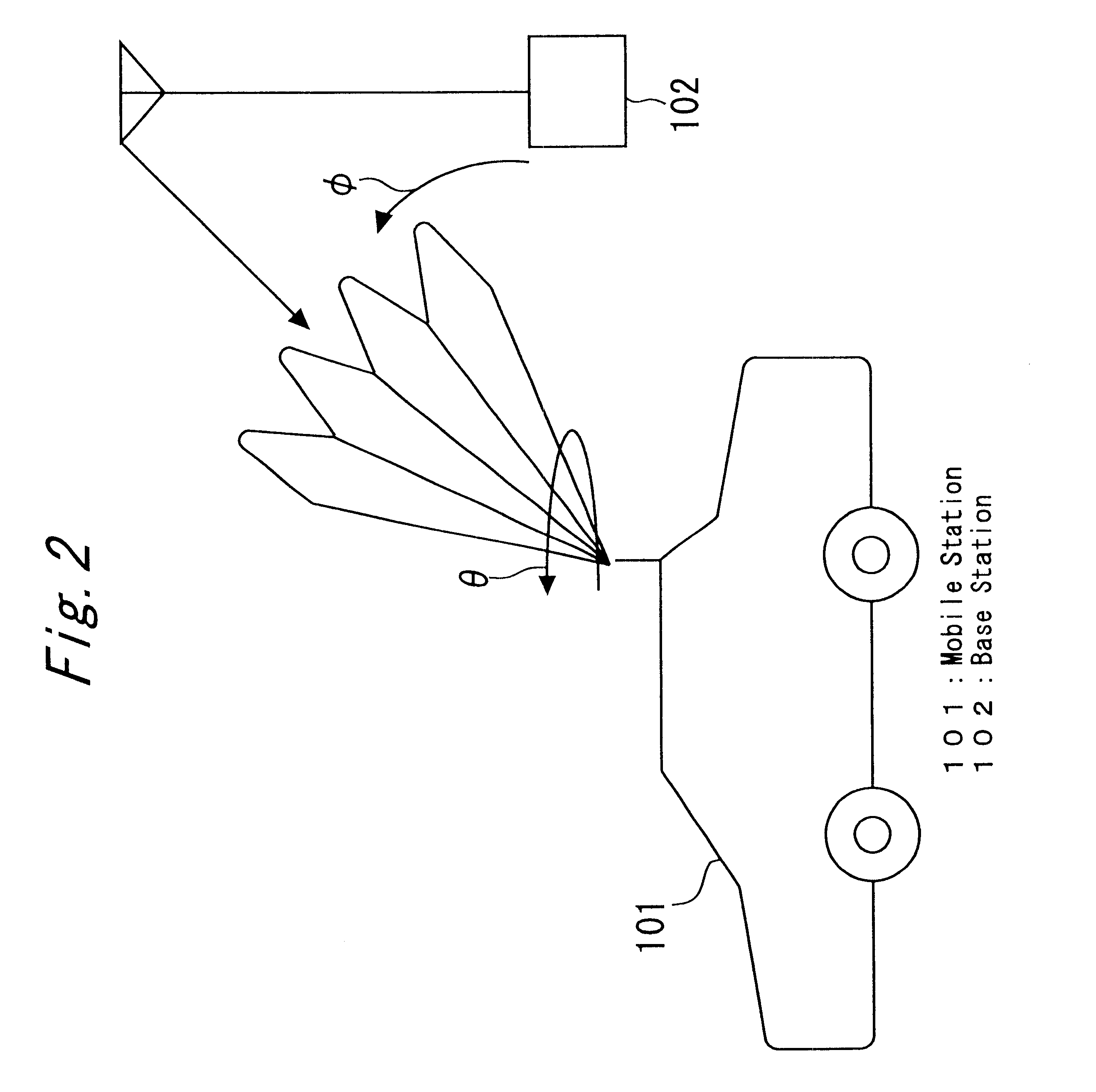
Further, according to the embodiment 1, the visiting area base station 102 varies a transmitting direction of a beam and the mobile station 101 varies the receiving direction, so a receiving side may receive a beam transmitted from the visiting area base station 102 more precisely. Thus, a receiving level of a narrow beam in the mobile station 101 becomes more strong, thereby interference from the adjacent base station 102 may be reduced in an area which a plurality of base stations overlap.

embodiment 2

On the other hand, when the visiting area base station 102 receives a reverse tracking channel from the mobile station 101, the visiting area base station 102 obtains the mobile station ID (step S0004), and then determines a transmitting direction of a beam by the same conventional method as shown in (6) of FIG. 5 and halts the irradiation operation of the narrow beam for searching (step S0005) and irradiates a narrow beam showing an end signal of a forward tracking channel by the forward tracking channel to the receiving direction as shown in (7) of FIG. 5 (step S0006).

Further, the visiting area base station 102 uses a frequency and a beam of a tracking channel without changing as shown in (8) of FIG. 5 to transmit an information channel (step S0007) and waits a receiving of an end signal of a reverse tracking channel from the mobile station 101 at the same time.

When the mobile station 101 receives an end signal of a forward tracking channel from the visiting area base station 102,...

embodiment 3

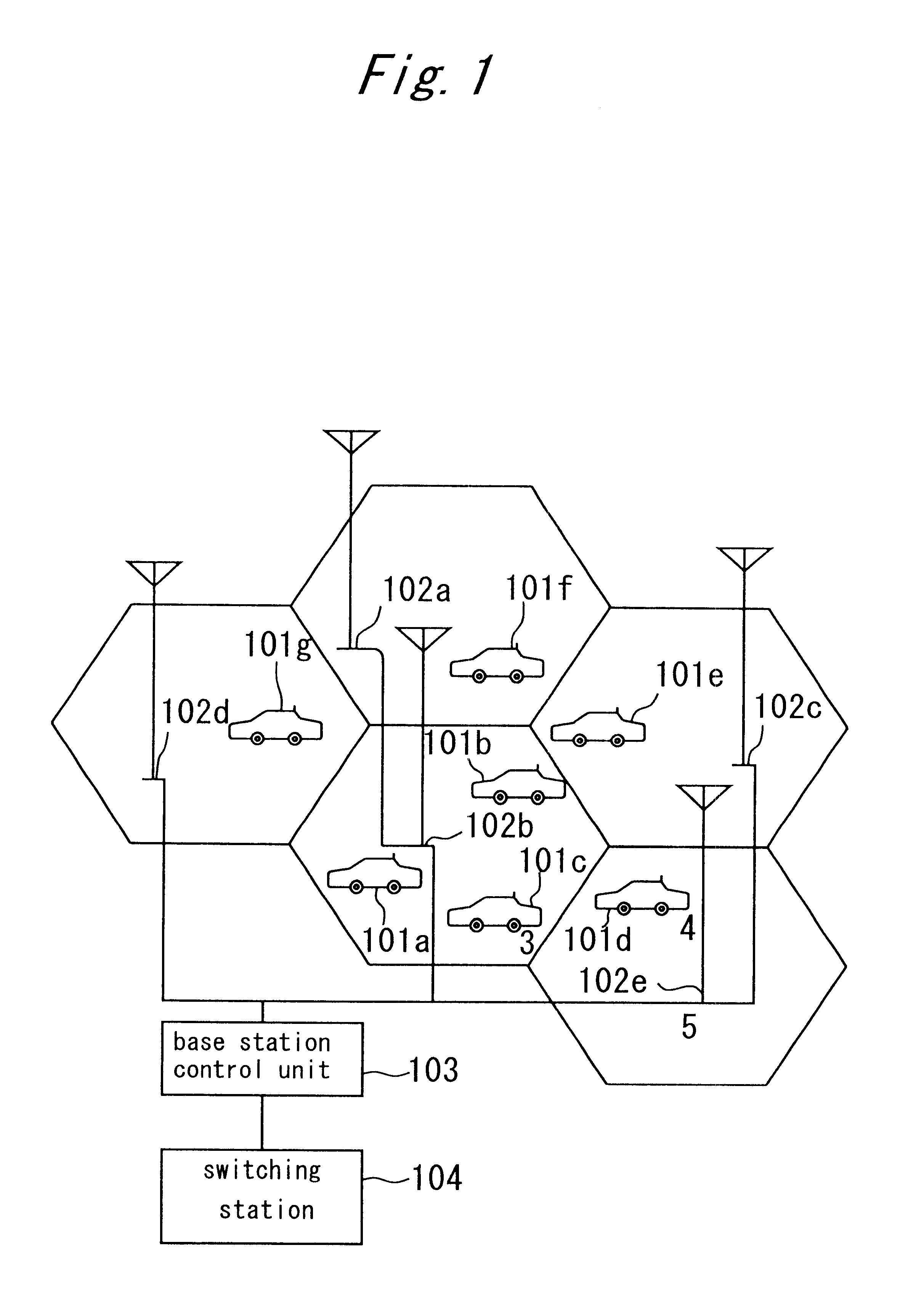
In the embodiment 3, a case which the mobile station 101 becomes to a communication state with the visiting area station 102 will be explained. As shown in FIGS. 6A and 6B, an information channel between the mobile station 101 and the visiting area station 102 is constituted by a plurality of frame 200 or the like. Further, control slots 214 or the like for controlling the mobile station 101 and the base station 102, tracking slots for searching the adjacent base station 102 (hereinafter referred to as searching slot) 210 or the like and information slots for transmitting information are provided in the frame 200 or the like.

As shown in FIG. 7, while the mobile station 101 communicates with the visiting area station 102, a searching is performed between the mobile station 101 and the adjacent base station 102 by controlling a receiving direction of a narrow beam at intervals of the above searching time slots as well as the embodiment 1, and a communication of both searching channel ...


PUM


Abstract

A mobile radio communication system which does not need an omnidirectional channel for both a base station and a mobile station to track each other and uses only a narrow beam channel and can reduce a tracking time than before for an adjacent base station and a mobile station to search each other while a visiting area base station and the mobile station are communicating in the overlapped area. The base station and the mobile station comprise a unit for transmitting and receiving in forward or reverse channel, in different frequency, in different tracking channel using a narrow beam. Both the mobile station and the visiting area base station search the location each other, and after searched, they assign the frequency and the beam used in the tracking channel. At the same time, by comprising a searching slot in an information channel to search an adjacent base station while communicating with the visiting area base station, a tracking of other adjacent base station can be performed.

Description

1. Field of the InventionThe present invention relates to, in a mobile radio communication system in which a base station and a mobile station under control of the base station have a tracking channel for tracking each other by a narrow beam, a tracking method between the mobile station and the base station (namely, a visiting area base station as it controls an area which the mobile station moves around), and a method of searching an adjacent base station while the mobile station communicates with the visiting area base station.2. Description of Related ArtFIG. 11 illustrates a configuration of a conventional "mobile radio communication system" described in Japanese Patent Application Laid-open No. Hei8-8814. In FIG. 11, reference numerals 1101a, 1101b and 1101c denote mobile stations; 1102 a base station; and 1103 an antenna of the base station 1102.Next, the operation will be explained. In FIG. 11, different frequency channels are assigned to each mobile station. For example, an ...

Claims


Application Information

Patent Timeline
Patent Type & Authority Patents(United States)
IPC IPC(8): H04Q7/36H04Q7/38H04B7/26H04W16/28H04W36/16
CPCH04W36/16H04W16/28
Inventor TAKE, KEIJIROITOU, SHUUJITOMISAWA, TOSHIAKI
Owner MITSUBISHI ELECTRIC CORP
Why Eureka
Try Eureka