Cursor control system with tactile feedback

a cursor control and tactile technology, applied in the direction of mechanical pattern conversion, instruments, cathode-ray tube indicators, etc., can solve the problems of limited pilot's ability to use touch, high visual awareness, and limited ability of presently known computer cursor pointing devices to provide feedback to users

Inactive Publication Date: 2002-04-16
HONEYWELL INC
View PDF7 Cites 108 Cited by
  • Summary
  • Abstract
  • Description
  • Claims
  • Application Information

AI Technical Summary

Problems solved by technology

This high visual awareness can present problems in an environment such as an aircraft cockpit where the user only has a limited amount of time to look at the GUI.
However, in modem cockpits, the relocation of control functionality to the GUI of a computer screen has limited the pilot's ability to use their sense of touch.
As already discussed, presently known computer cursor pointing devices are limited in their ability to provide feedback to the user.
However, in a noisy cockpit, the aural feedback can easily be muffled by ambient noise.
The need to visually locate a pointer on the GUI has led to an increased heads down time for the pilot.
This increased heads down time can lead to a reduced ability to maintain situational awareness.
However, these prior art devices suffer from a number of practical limitations.
This mouse would be of limited use in an environment where space is limited, e.g., an aircraft cockpit.
The above prior art mouse is also limited in that it only provides one type of tactile feedback, i.e., the protruding pin.
A single type of tactile feedback is incapable of distinguishing between different areas of the GUI or different operations performed by the user.
Another limitation of the above prior art mouse is that the user must keep his or her finger over the hole at all times in order to feel the protruding pin.
This is not useful in an environment such as an aircraft cockpit where such delicate manipulation of a mouse is not feasible.
However, this touchpad device is also limited as it is merely configured to provide tactile feedback to simulate a mouse button press and release.
This touchpad device does not allow the user to reduce their visual awareness of the GUI by providing tactile feedback when the pointer is over a selectable component of the GUI such as a menu button.
For example, when the cursor or pointer indicates a selectable component of the GUI, the cursor control system may cause the pointing device to vibrate, shake, or the like.

Method used


Image

  • Cursor control system with tactile feedback
  • Cursor control system with tactile feedback
  • Cursor control system with tactile feedback

Examples


Embodiment Construction

The subject matter of the present invention is particularly suited for use in connection with aircraft cockpits. As a result, the preferred exemplary embodiment of the present invention is described in that context. It should be recognized, however, that such description is not intended as a limitation on the use or applicability of the present invention, but is instead provided merely to enable a full and complete description of a preferred embodiment. On the contrary, various aspects of the present invention may be applied to a wide array of uses.

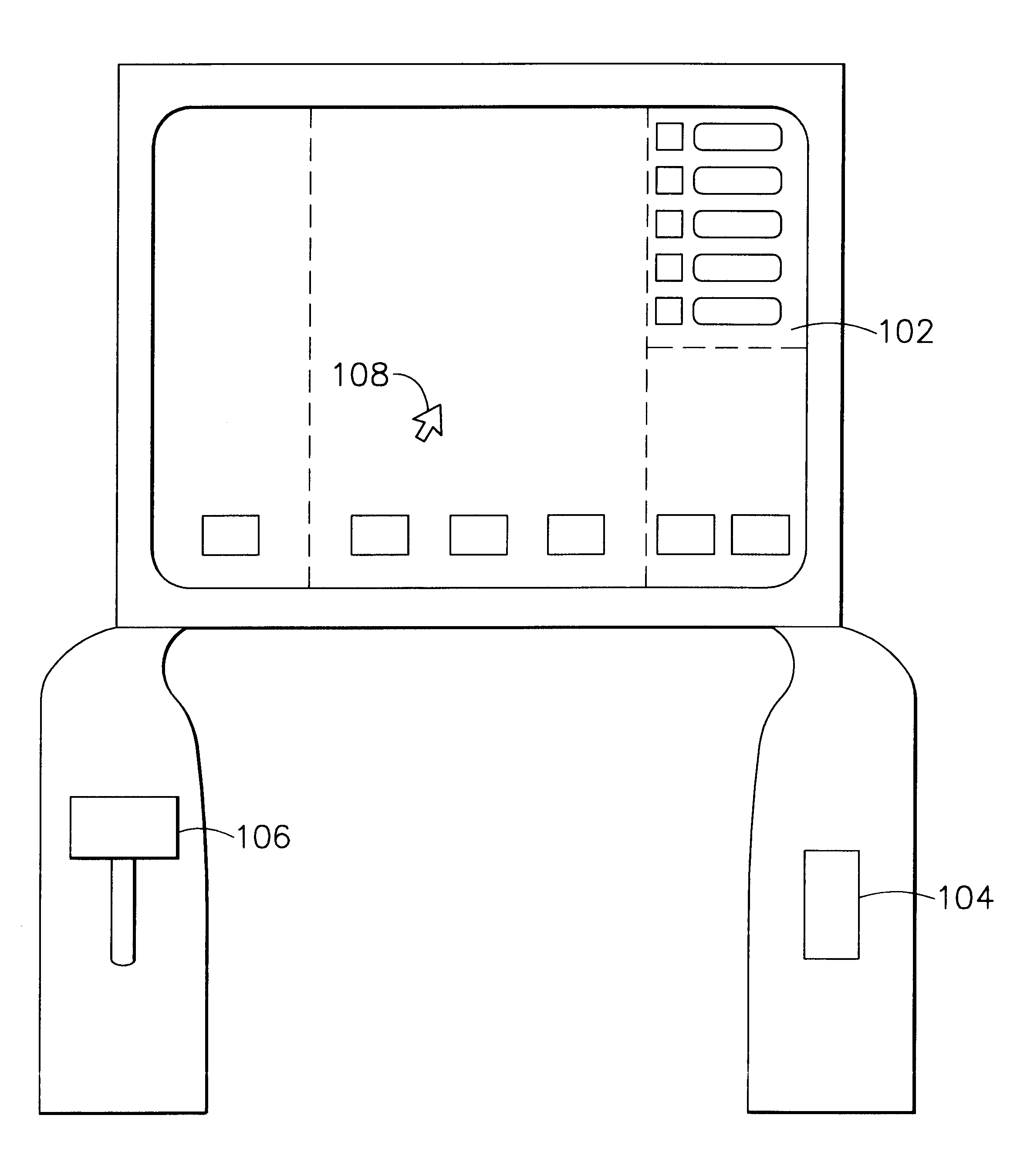
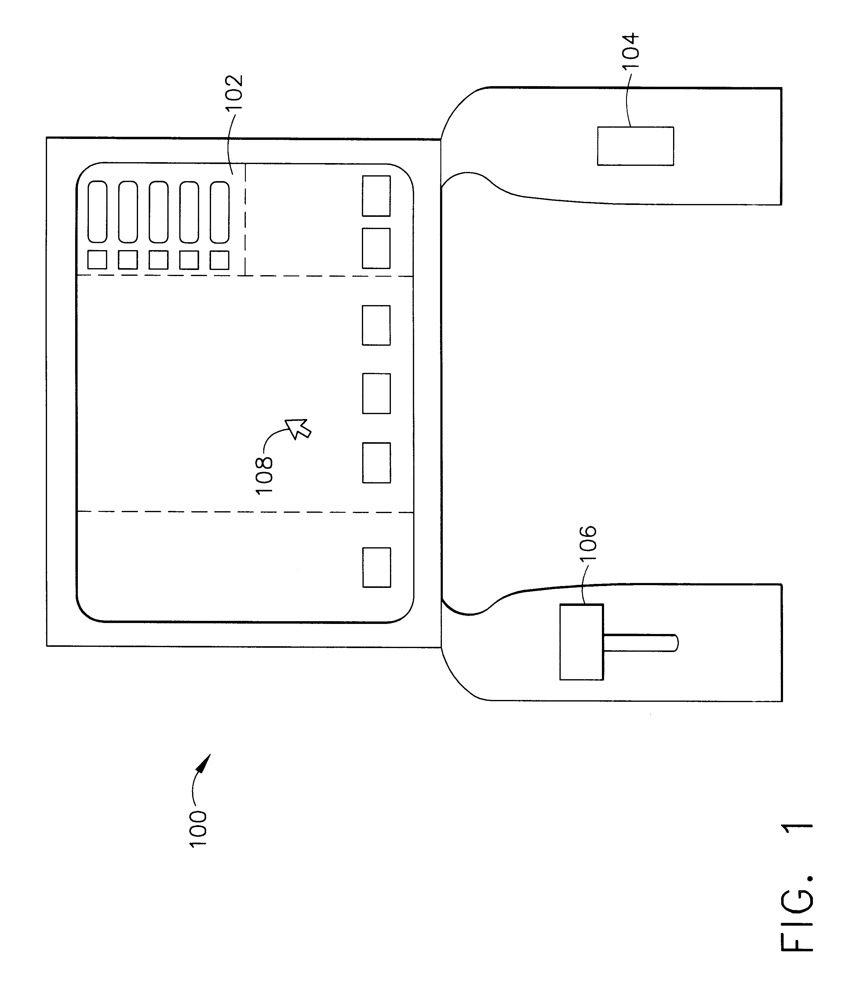
Referring now to FIG. 1, a representative layout of an aircraft cockpit 100 includes a display 102, a pointing device 104, and a throttle 106. The pilot uses the pointing device 104 to manipulate a pointer 108 that is generated by the particular software application and rendered on the display 102. The pointing device 104 could be a joystick, trackball, touchpad, mouse or some other type of computer cursor pointing device.

Referring now to...


PUM


Abstract

A cursor control system suitable for interactive use with an application program, and in response to specific conditions associated with the application program, the cursor control system provides tactile feedback that can be felt by the user. In particular, when the cursor or pointer indicates a selectable component of the Graphical User Interface (GUI), the cursor control system will provide tactile feedback to the user. In addition, when a valid selection is made on the GUI, the cursor control system will also provide tactile feedback to the user.

Description

1. Field of the InventionThe present invention generally relates to computer cursor pointing devices, and, more particularly, to computer cursor pointing devices with tactile feedback.2. Description of the Related ArtIn many computer applications, the current trend is toward moving the user interface to a graphical user interface (GUI). When using a GUI, the user accesses the functionality of the computer application by manipulating a computer-generated pointer rendered on the display screen. One way that the user manipulates the pointer is by maneuvering a computer cursor pointing device. Devices used for this operation to date include joysticks, trackball devices, mouse devices, and touchpad devices. The pointer on the screen tracks the movement of the computer cursor pointing device. For example, when using a touchpad, the pointer on the screen will track the movement of the user's finger on the touchpad. When the pointer is over a selectable component of the GUI such as a menu b...

Claims


Application Information

Patent Timeline
IPC IPC(8): G06F3/033G06F3/00G06F3/01
CPCG06F3/016G06F3/03547G06F2203/014
Inventor BEEKS, DOUGLAS W.
Owner HONEYWELL INC
Why Eureka
Try Eureka