Engine decompression device

a decompression device and engine technology, applied in the direction of engine starters, valve arrangements, muscle operated starters, etc., can solve the problems of inability to dispose of the decompression actuator therebetween in the outboard motor engine, the engine stall is quite likely to occur during the trolling operation, and the difficulty of the engine to be able to operate normally

Inactive Publication Date: 2002-04-23
SANSHIN KOGYO CO LTD
View PDF5 Cites 18 Cited by
  • Summary
  • Abstract
  • Description
  • Claims
  • Application Information

AI Technical Summary

Problems solved by technology

That is, the decompression device must be released promptly when engine is started and not work above a selected idle engine speed.
However, some problems are caused by this particular use and a special structure of the engine for the outboard motor.
This is extremely difficult.
If, however, the releasing speed is not stable under the trolling speed, an engine stall is quite likely to occur during the trolling operation.
This particular construction consequently results in the sinker on the decompression device being significantly influenced by gravity and, therefore, adds another problem: the center of gravity in the decompression actuator must be determined by carefully selecting a proper weight for and a position of the sinker in consideration of the influence of gravity so that the decompression actuator will release at a slow rotational speed.
In addition, due to a relatively small and restricted space between an intake valve and an exhaust valve, the decompression actuator usually cannot be disposed therebetween in outboard motor engines.
However, it is complicated and difficult to release the actuator properly in the latter construction, because the cam section is placed upper than the pivot axis of the actuator.

Method used


Image

  • Engine decompression device
  • Engine decompression device
  • Engine decompression device

Examples


Embodiment Construction

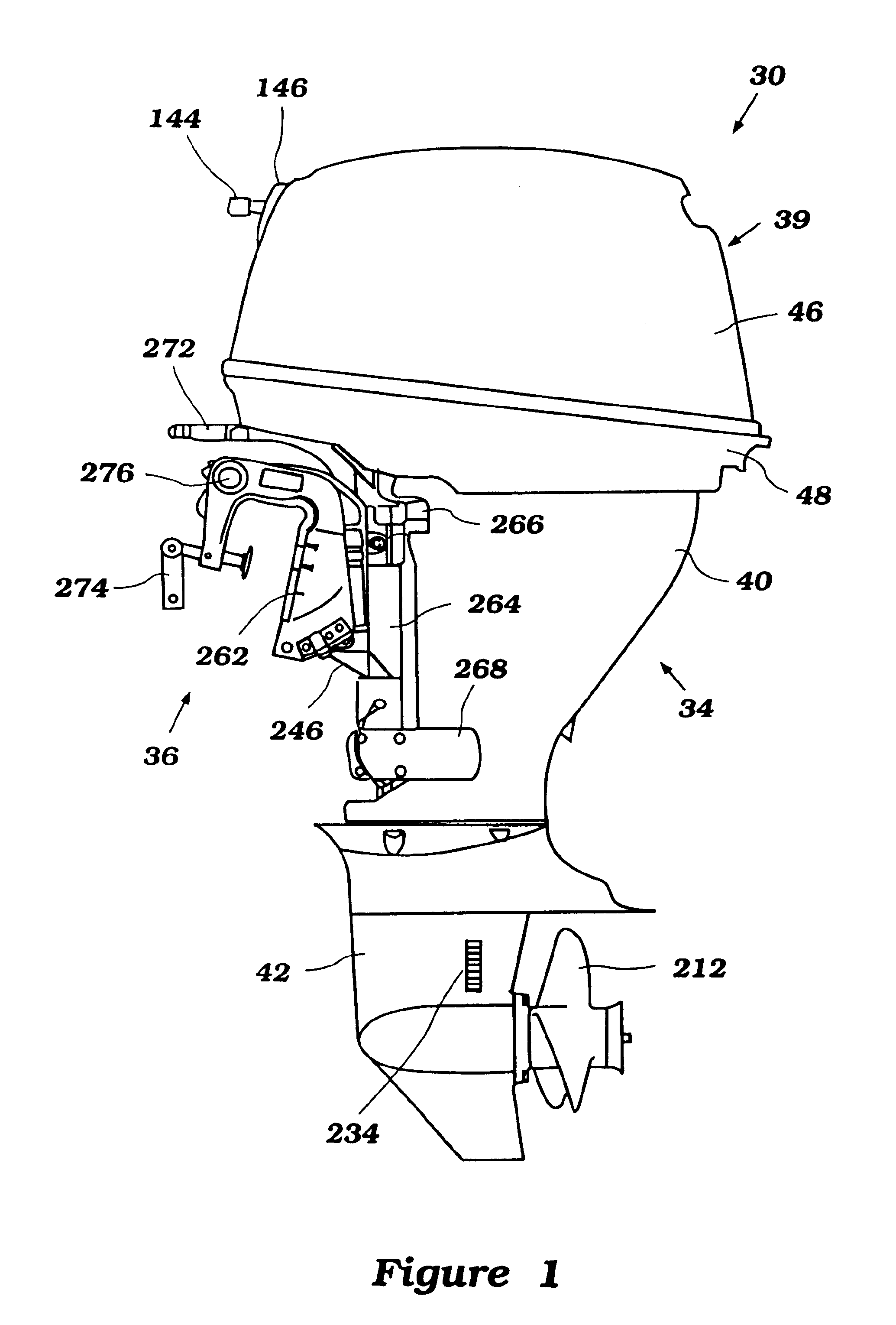
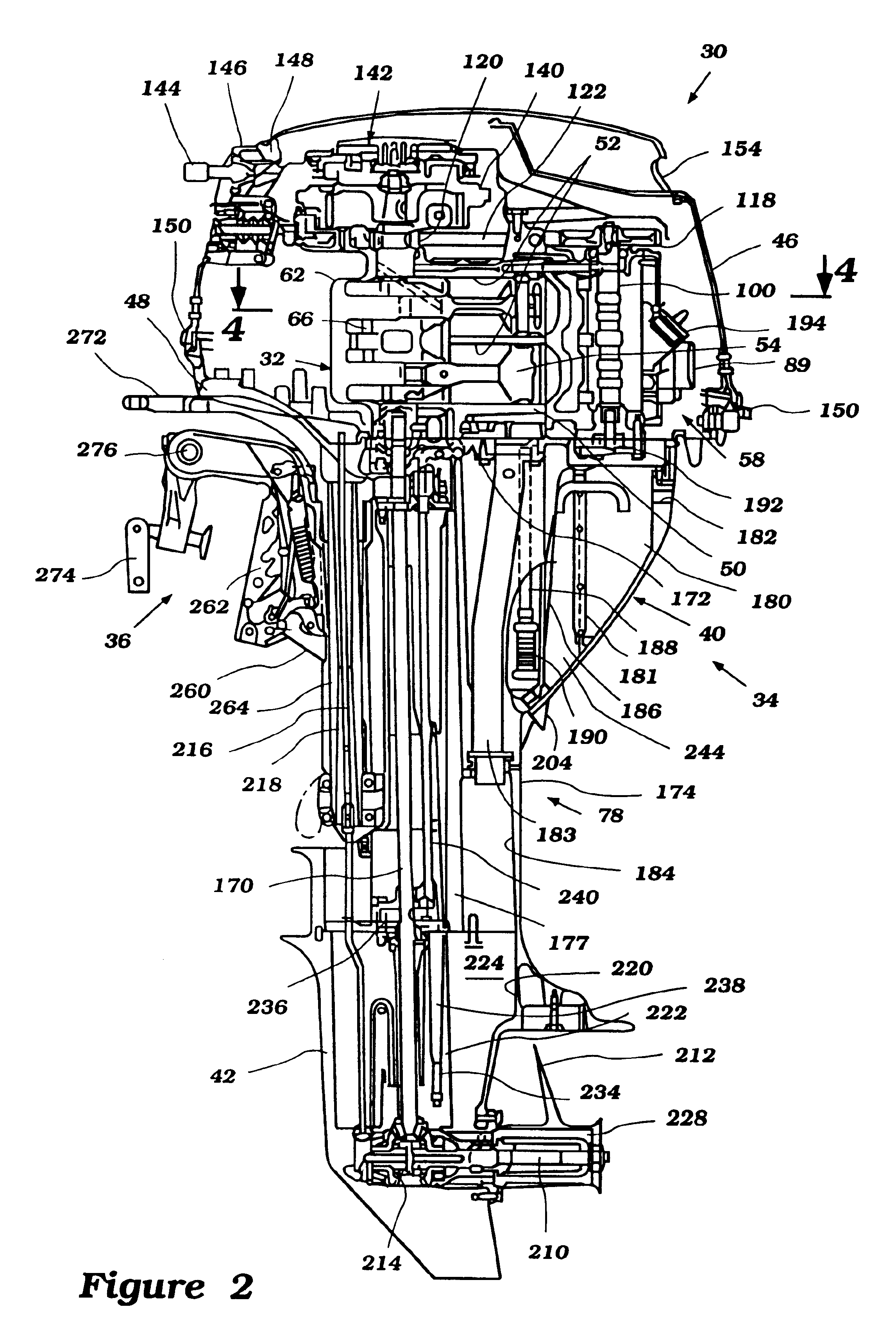
With reference to FIGS. 1 to 5, an outboard motor, designated generally by the reference numeral 30, includes an internal combustion engine 32 arranged in accordance with a preferred embodiment of this invention. Although the present invention is shown in the context of an engine for an outboard motor, various aspects and features of the present invention also can be employed with other types of engines used for such as, for example, a marine stern drive systems and land vehicles.

In the illustrated embodiment, the outboard motor 30 comprises a drive unit 34 and a bracket assembly 36. The drive unit 34 can be affixed to a transom of an associated watercraft by the bracket assembly 36.

The drive unit 34 includes a power head 39, a driveshaft housing 40 and a lower unit 42. The power head 39 is disposed atop of the drive unit 34 and includes the engine 32, a top protective cowling 46 and a bottom protective cowling 48.

The engine 32 operates on a four stroke cycle principle and powers a ...


PUM


Abstract

An engine decompression device includes an improved construction to release at an exceedingly slow engine speed. The engine has a camshaft that actuates at least one exhaust valve and extends generally vertically. The decompression device has an actuator mounted on the camshaft for pivotal movement about a pivot axis extending generally normal to an axis of the camshaft. The actuator includes a cam section that holds the exhaust valve in an open position and a sinker section that moves with centrifugal force produced by relatively slow rotation of the camshaft so as to release the cam section from holding the exhaust valve open.

Description

PRIORITY INFORMATIONThe present application is based upon and claims priority to Japanese Patent Application No. Hei 11-026989, filed Feb. 4, 1999, the entire contents of which is hereby expressly incorporated by reference.1. Field of the InventionThis invention relates to an engine decompression device, and more particularly to an improved decompression device that is suitable for marine engines.2. Description of Related ArtIn many engine applications, the operator may be required to manually start an internal combustion engine. This may be true whether or not the engine is also provided with an electrical or otherwise operated self-starting mechanism. For instance, it is frequently the practice in outboard motors, and particularly those of small displacement, to incorporate a mechanism whereby the engine may be manually started. This is normally done by a rope or recoil starter mechanism that is associated with a flywheel on the upper end of the crankshaft.However, in order to ach...

Claims


Application Information

Patent Timeline
Patent Type & Authority Patents(United States)
IPC IPC(8): F01L13/08F02B61/00F02B61/04F02N3/04
CPCF01L13/08F02B61/045F02B2275/18F01L2001/0537
Inventor SUZUKI, HIROYUKIYUKISHIMA, KENJI
Owner SANSHIN KOGYO CO LTD
Why Eureka
Try Eureka