Fuel and air purge system for diaphragm carburetors

a diaphragm carburetor and air purge system technology, which is applied in the direction of carburettors, machines/engines, and charge feed systems, etc., can solve the problems of air purge feed holes not removing enough air/vapor from the metering chamber, and the stability of all position idle and acceleration. , to achieve the effect of reducing the presence of gaseous phas

Inactive Publication Date: 2002-04-23
WALBRO ENGINE MANAGEMENT
View PDF6 Cites 26 Cited by
  • Summary
  • Abstract
  • Description
  • Claims
  • Application Information

AI Technical Summary

Benefits of technology

Accordingly, among the objects of the present invention are solving one or more of the foregoing problems by providing a new and improved method of reducing gaseous phase presence in the liquid fuel metering of a diaphragm carburetor for an internal combustion engine, such as in the form of excessive air or

Problems solved by technology

Carburetor manufacturers therefore have been challenged to provide diaphragm carburetors, both rotary valve carburetors (RVC) and cubic butterfly valve type, for this market.
This process has been mostly successful although performance problems have surfaced related to all position idle stability and acceleration.
The problems described above are not as apparent on two-stroke engine applications since two stroke engines consume about three times as much fuel at idle and wide open throttle (WOT) as four-stroke engines.
Further, since these engines may tend to run hotter than their two-stroke counterparts, the four-stroke engine carburetors experience an additional heat load which contributes to vaporization of the fuel in the metering chamber.
As a result, the air purge feed hole may not remove enough air/vapor from the metering chamber when oper

Method used


Image

  • Fuel and air purge system for diaphragm carburetors
  • Fuel and air purge system for diaphragm carburetors
  • Fuel and air purge system for diaphragm carburetors

Examples


first embodiment

of the Invention

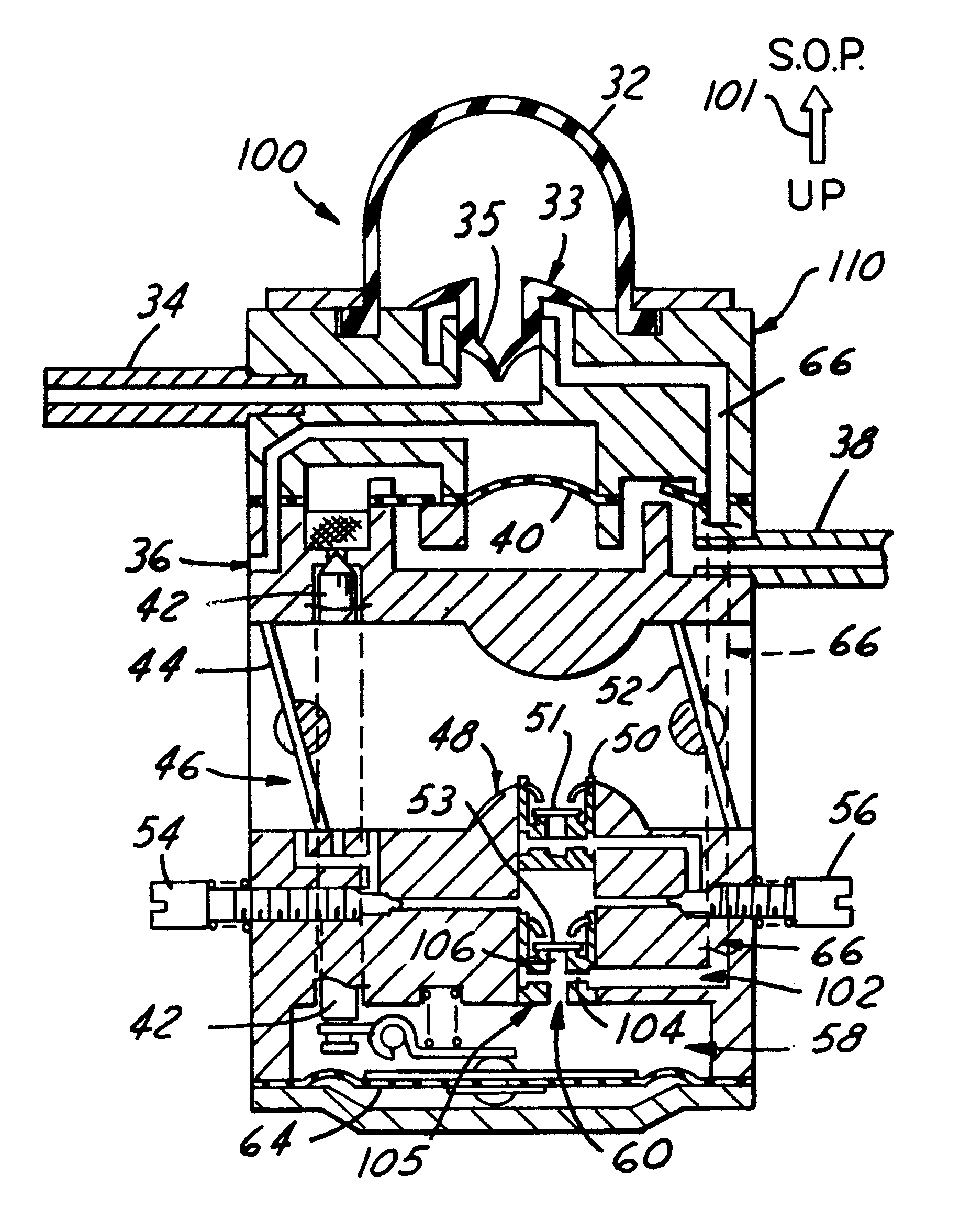
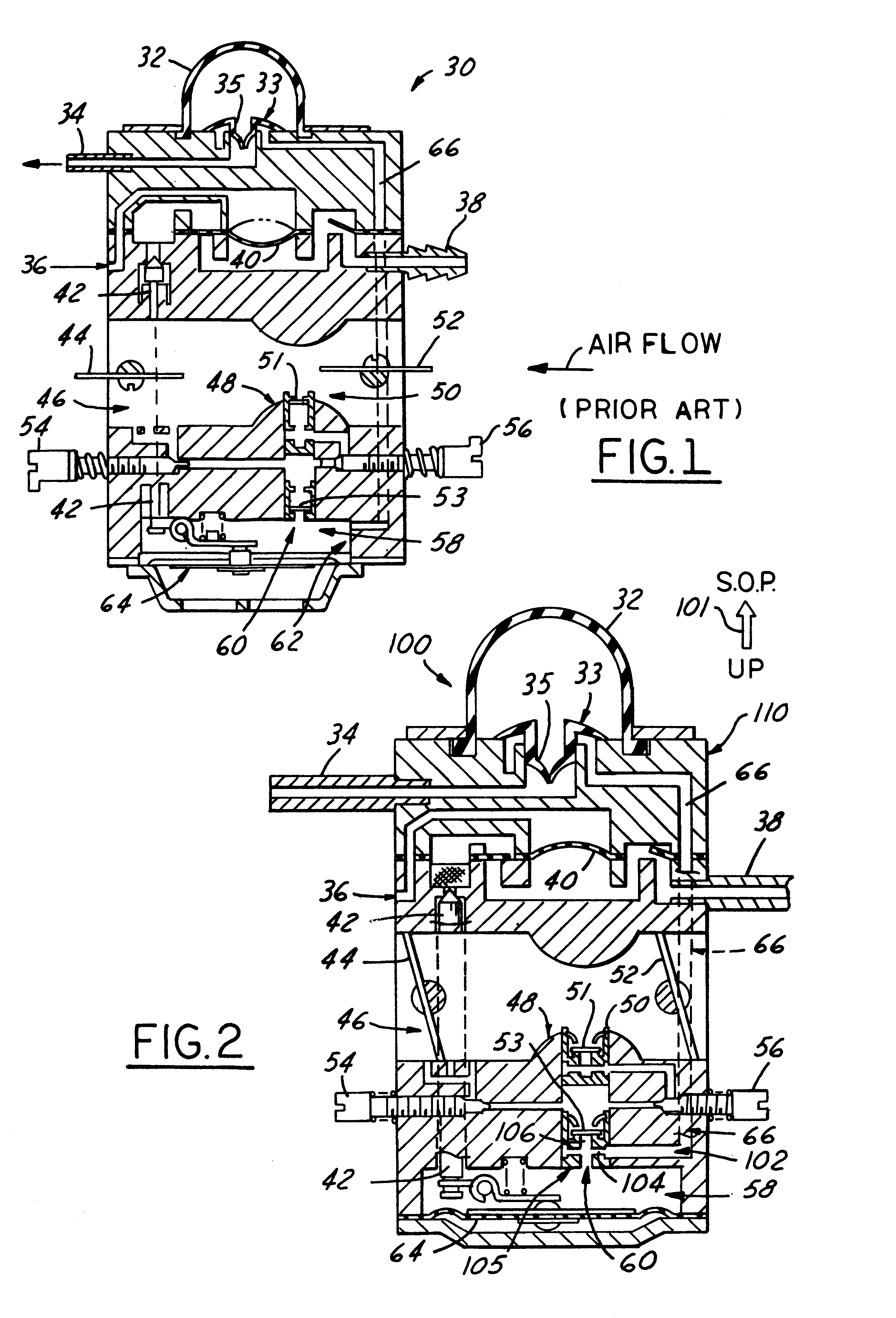
FIG. 2 illustrates schematically the same type of diaphragm carburetor as described and illustrated in connection with the prior art carburetor 30 of FIG. 1, but modified in accordance with the method of the invention to provide an improved carburetor 100 of the invention capable of solving the aforementioned problems and thereby achieving all-position idle stability for mini-four-stroke engines while yet utilizing a diaphragm carburetor of current design and manufacture as intended initially and primarily for use on two-stroke single cylinder engines. Those elements of carburetor 100 common to carburetors 30 and 100 are given the same reference numerals and their description not repeated. Thus, it will be seen that, in accordance with the method of invention, a diaphragm type carburetor 100 is provided having the usual components and generally arranged into the same organization and functioning in for cooperation to work in generally the same mode of operation as th...

second embodiment

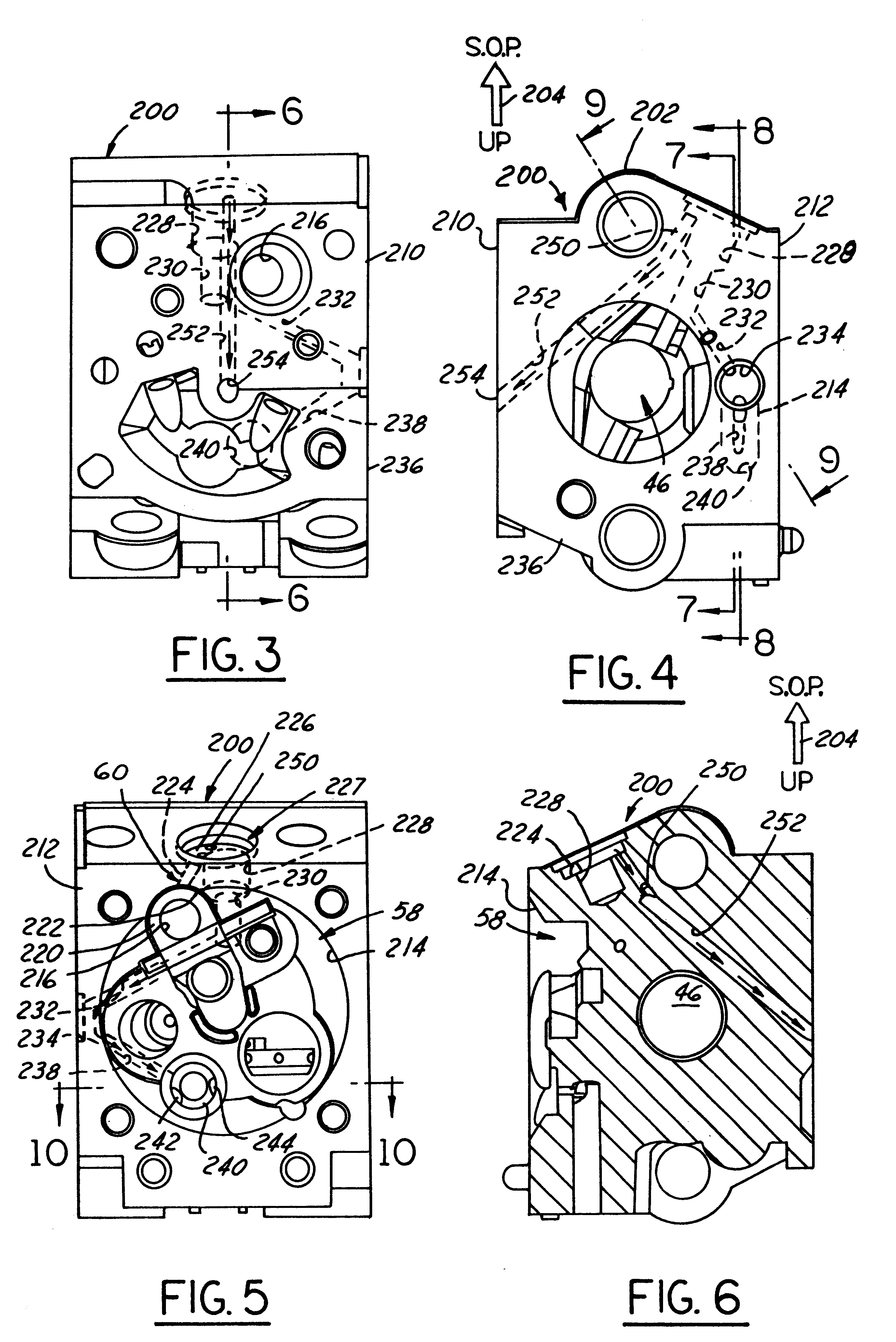
Accordingly, as shown in FIGS. 16-28 the prior art RVC carburetor 300 is modified to operate satisfactorily in the SOP orientation of arrow 301 in FIG. 14 in accordance with the method of the invention to thereby render carburetor 300 operable to perform under this new condition of predetermined reorientation of the standard operating position. All that needs to be done is to modify the pump and metering chamber body 306 in the manner shown in the engineering machine views of FIGS. 16-28 and as described hereinafter to provide the modified body 306'. Again, it is to be noted that these views are from machining drawings and are drawn to engineering scale, and the same incorporated herein by reference to supplement the description and disclosure, and likewise as to the previously referenced engineering machining views of FIGS. 3-13.

More particularly, it will be seen that the modified pump and metering chamber body 306' that is to be substituted for body 306 in carburetor 300 in accord...


PUM


Abstract

A method of reducing gaseous phase presence in the liquid fuel metering chamber of a diaphragm by providing a "High-Point Pick Up" hole positioned in the optimal metering chamber location (highest) to assure maximum purge evacuation of air and/or other gases prior to engine start-up and during running. This optimal location is dependent upon first determining, in advance of carburetor fuel feed circuitry and/or air purge system design, the orientation of the carburetor as mounted on the engine in its primary operator usage position, or so-called "standard operating position" (SOP). This SOP in turn is determined in the first instance by the engine manufacturer and/or the manufacturer of the portable engine-driven handheld appliance on which the engine is mounted. In one embodiment the two typical fluid circuits (air purge and normal idle/high speed fuel feed circuits) share a common, sole take-off inlet opening into the metering chamber, the same being located at the highest elevation point in the metering chamber in the given SOP orientation. This assures that the maximum amount of air and/or fuel vapor is removed from the metering chamber during purging prior to start-up and during running. In accordance with the invention, the primary usage position (SOP orientation) of the engine is determined and becomes a known use parameter prior to the carburetor manufacturer determining such take-off hole location. Both butterfly valve cubic carburetor and rotary valve carburetor embodiments are disclosed embodying the invention.

Description

This invention relates to fuel and air purge systems for diaphragm carburetors adapted for use on internal combustion engines, and more particularly for use on small single cylinder four-stroke engines adapted for use on hand-held engine-driven appliances.As a result of emission control legislation in the United States, handheld engine manufacturers have developed various solutions to the tighter exhaust emission limits. One solution is the use of mini-four stroke engines. The 25 to 30 cc mini four-stroke engine market is growing and many manufacturers are using this engine design as opposed to alternative two-stroke technology. Carburetor manufacturers therefore have been challenged to provide diaphragm carburetors, both rotary valve carburetors (RVC) and cubic butterfly valve type, for this market. For cost and other reasons such as proven performance and reliability, the approach has been to calibrate diaphragm carburetors of the type used on two-stroke engines of the same size. ...

Claims


Application Information

Patent Timeline
IPC IPC(8): F02M17/00F02M17/04F02M37/20
CPCF02M17/04F02M37/20
Inventor PATTULLO, GEORGE M.
Owner WALBRO ENGINE MANAGEMENT
Why Eureka
Try Eureka