Retaining device for a side cover of a computer casing

Inactive Publication Date: 2002-04-23
LAI VINCENT
View PDF11 Cites 48 Cited by
  • Summary
  • Abstract
  • Description
  • Claims
  • Application Information

AI Technical Summary

Problems solved by technology

When necessary, the user will have to use a screw driver to unscrew the side cover from the casing, which is time consuming and labor inefficient.
However, separating the engagemen

Method used


Image

  • Retaining device for a side cover of a computer casing
  • Retaining device for a side cover of a computer casing
  • Retaining device for a side cover of a computer casing

Examples


Embodiment Construction

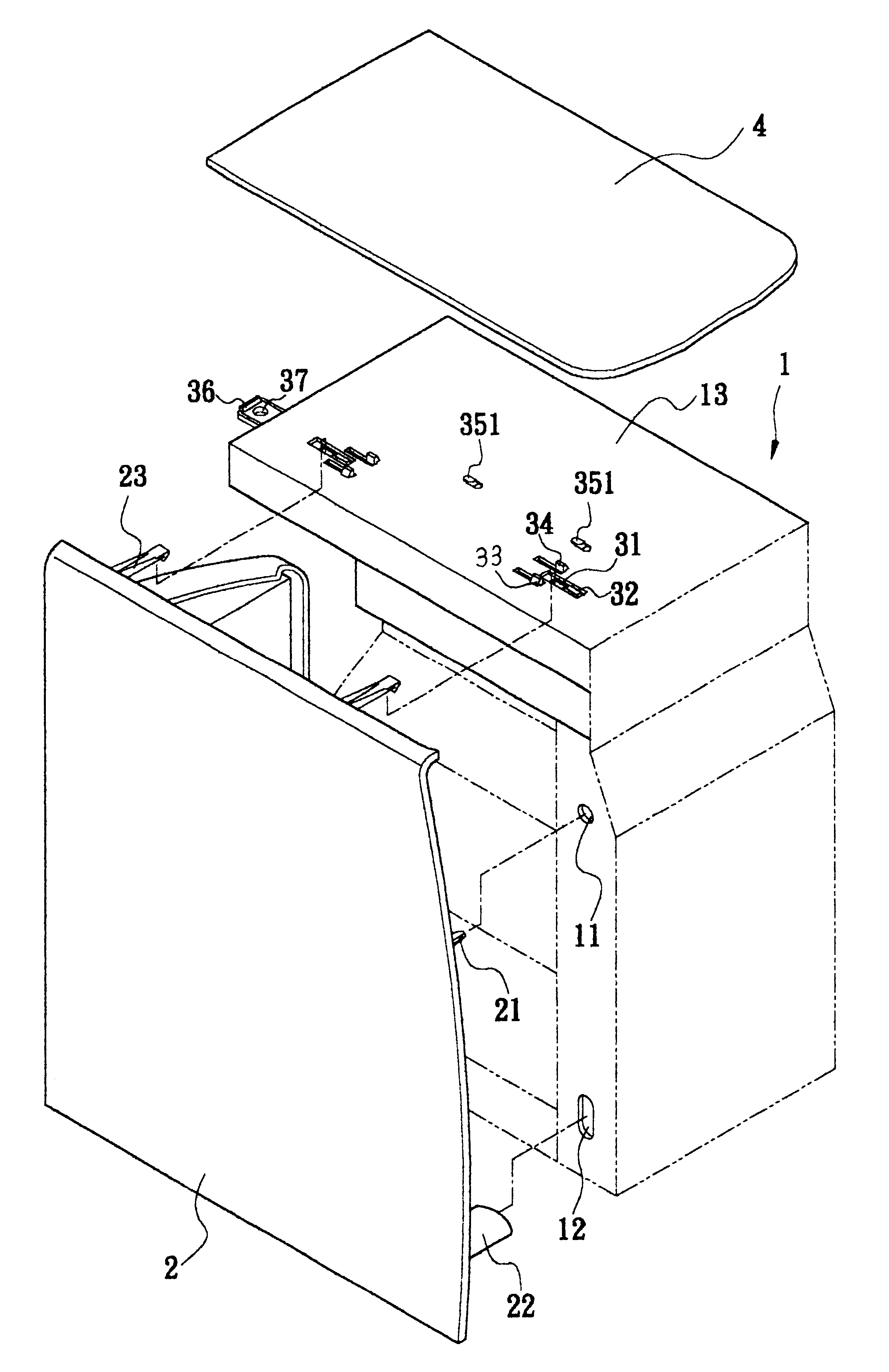
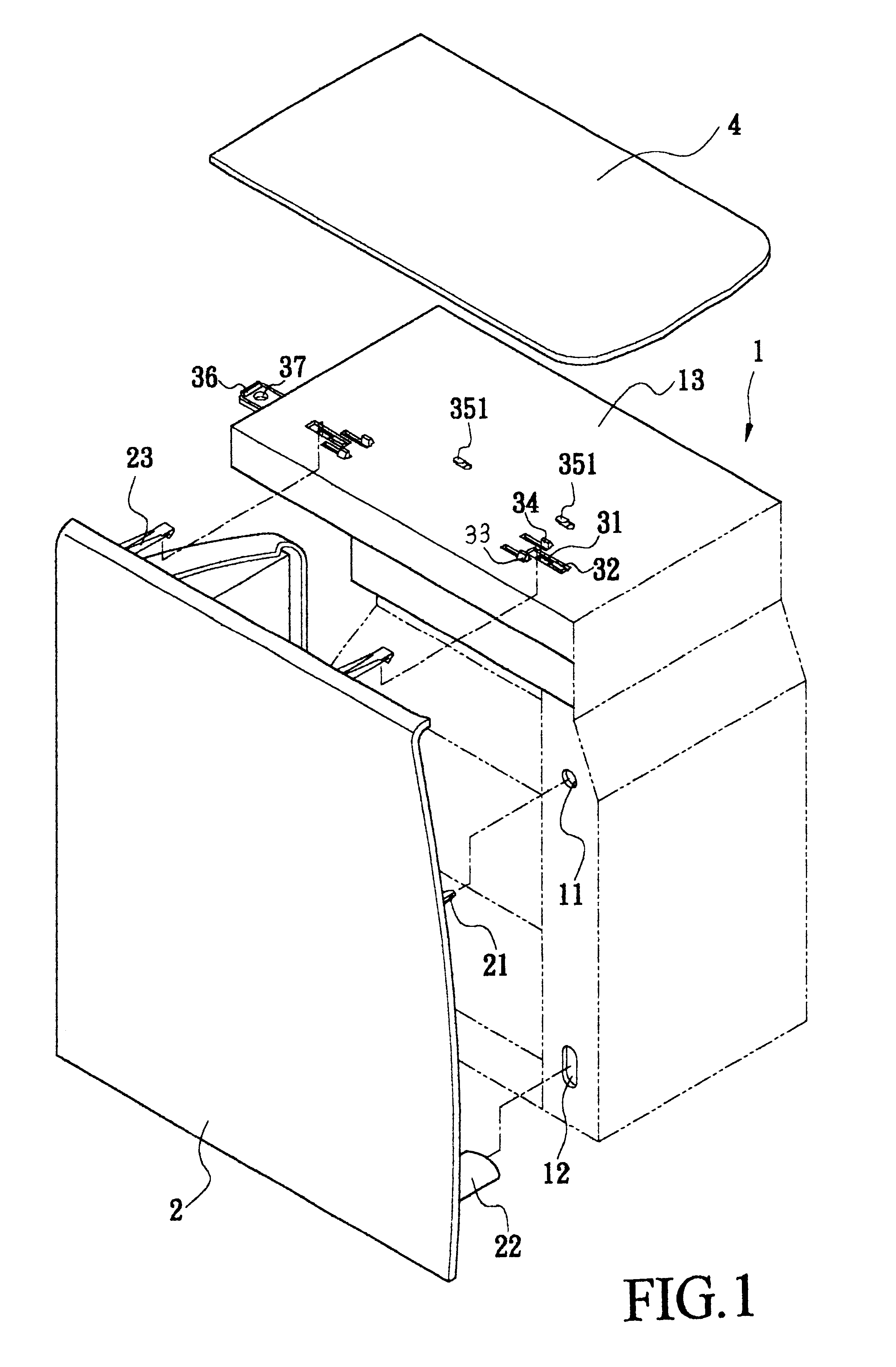
With reference to FIGS. 1, a computer casing (1) has a side cover (2) detachably connected to the computer casing (1) by means of a retaining device constructed in accordance with the present invention. The computer casing (1) has a first positioning hole (11) and a second positioning hole (12) respectively defined in a side face thereof. The side cover (2) has a first rod (21) extending out to correspond to the first positioning hole (11) and a second rod (22) extending out to correspond to the second positioning hole (12). With the insertion of the first and the second rods (21,22) into the corresponding first and second positioning holes (11,12), the side cover (2) is able to be temporarily positioned.

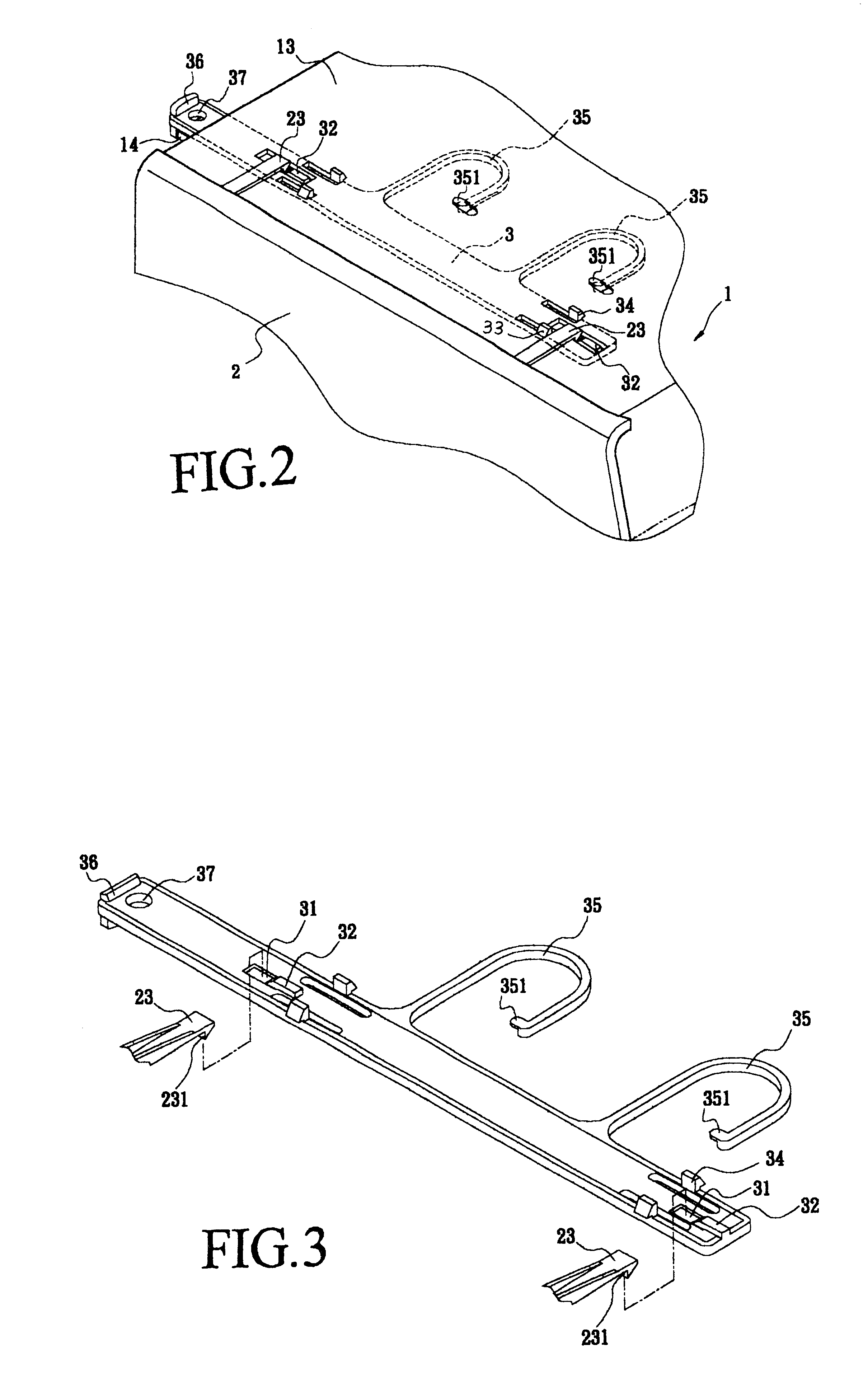
With reference to FIGS. 2 and 3 and still taking FIG. 1 for reference, the retaining device has a sliding plate (3) movably secured beneath a top face (13) of the casing (1) and having a set of extensions (23) securely mounted to the side cover (2). The sliding plate (3) has a cutou...


PUM


Abstract

A retaining device for a side cover of a computer casing has a sliding plate movably received beneath the top face of the computer casing and a set of extensions formed on the side cover. The sliding plate has a wedged block formed to detachably engage with distal ends of the extensions. The movement of the sliding plate allows the wedged block to engage with the distal ends of the extensions of the side cover to push away the side cover from the computer casing. Therefore, the side cover is separated from the computer casing readily.

Description

1. Field of the InventionThe present invention relates to a retaining device of a computer casing, and more particularly to a retaining device for a side cover of a computer casing. The retaining device has a sliding plate movably secured beneath the top face of the computer casing and a set of extensions respectively mounted on the side cover. The sliding plate has a wedged block formed thereon and detachably engaged with distal ends of the extensions. With such an arrangement, the user is able to detach the side cover from the computer casing easily.2. Prior Art DescriptionA conventional side cover of a computer casing normally is screwed onto the casing. When necessary, the user will have to use a screw driver to unscrew the side cover from the casing, which is time consuming and labor inefficient. To overcome the drawback, a snapping hook is provided to the side cover, which is corresponding to the hole defined in the casing, such that when necessary, the user can detach the sid...

Claims


Application Information

Patent Timeline
IPC IPC(8): G06F1/18H05K5/00
CPCH05K5/0013G06F1/181Y10T292/432
Inventor LAI, VINCENT
Owner LAI VINCENT
Why Eureka
Try Eureka