High efficiency heat removal system for rack mounted computer equipment

Inactive Publication Date: 2009-10-22
NEUDORFER JULIUS
View PDF33 Cites 95 Cited by
  • Summary
  • Abstract
  • Description
  • Claims
  • Application Information

AI Technical Summary

Benefits of technology

[0032]Cooling liquid may be returned from the cooling fluid heat transfer assembly to through a heat exchanger which cools the liquid before it is returned to the rack. The heat exchanger may be cooled by a mechanical chiller system and may be located remotely from

Problems solved by technology

This will result in a substantial decrease in the a

Method used


Image

  • High efficiency heat removal system for rack mounted computer equipment
  • High efficiency heat removal system for rack mounted computer equipment
  • High efficiency heat removal system for rack mounted computer equipment

Examples


Embodiment Construction

[0059]Hereinafter, embodiments of the present invention will be described in detail with reference to the accompanying drawings. Note that components having the same function are denoted by the same reference symbols throughout the drawings for describing the embodiments, and the repetitive description thereof is omitted.

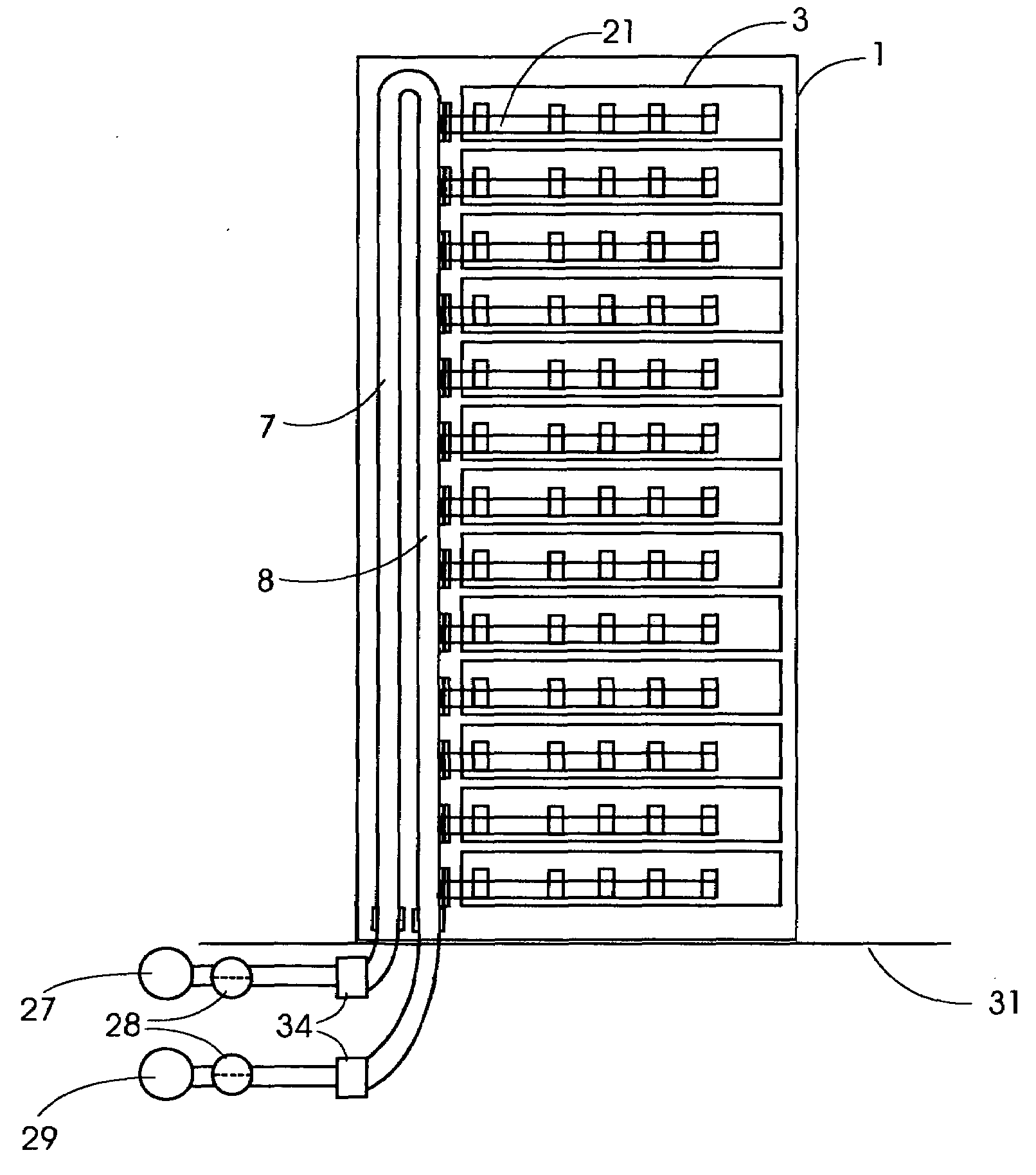
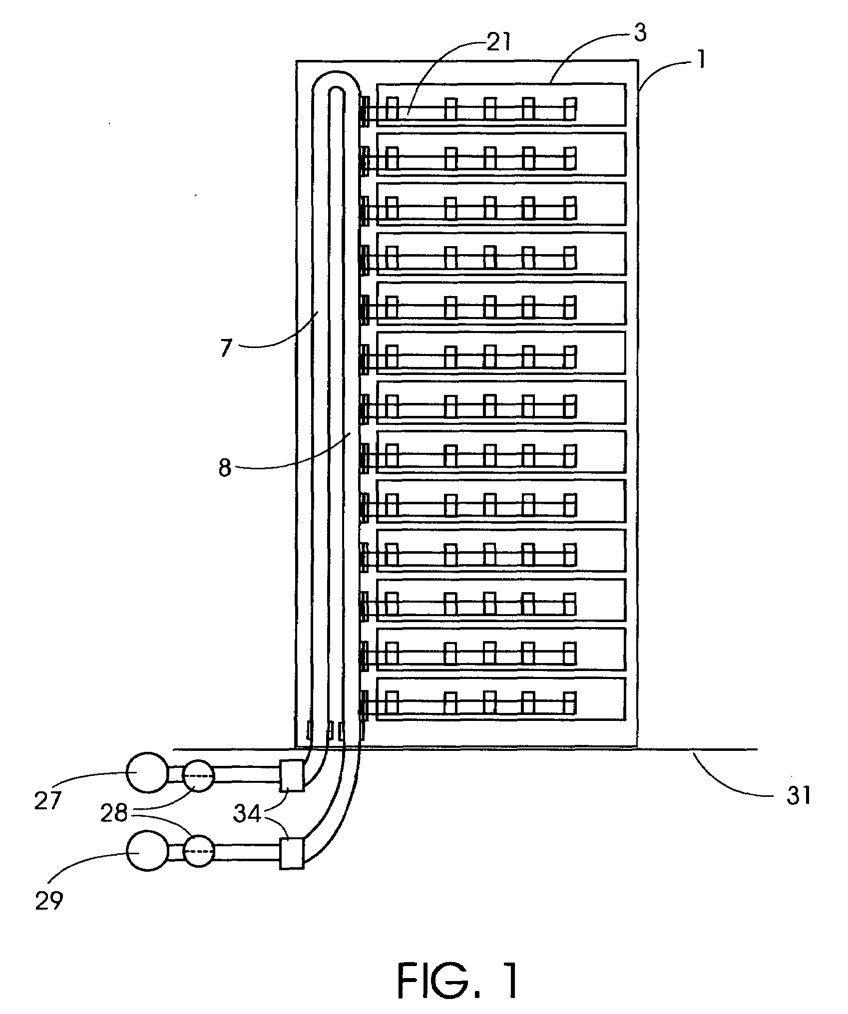
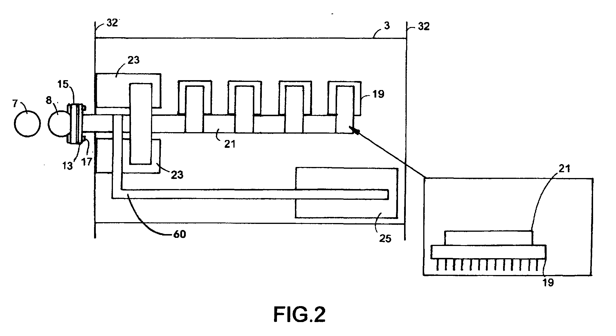
[0060]The preferred embodiment of the cooling system for the rack-mount computer equipment such as a server system schematically shown in FIG. 1 and includes: a rack cabinet 1; a plurality of computer equipment cases 3 (such as typically used for servers) provided with a heat transfer conduit 21 in the server(s), and the like; a cooling fluid heat transfer assembly located within the rear of a rack cabinet which may be composed of a at least one outflow return warm fluid pipe 7, and at least one inflow cold fluid pipe 8; said piping may be shaped to efficiently transfer heat such as, but not limited to square, rectangular, oval, round shaped pipes and may be coupled...


PUM


Abstract

An efficient method of heat removal from rack mounted computer equipment, network gear and other electronic equipment, consisting of solid heat conducting components in direct contact with the heat generating sources. In particular, this invention is primarily focused on the ability to efficiently and effectively cool computer equipment in standard computer rack cabinets.
This invention utilizes a design that retains the general existing form factor of the rack mounted computer equipment, but uses direct contact heat transfer to a metal heat transfer conduit (Copper, Aluminum or other metal or efficient heat conducting material) contained within the computer equipment chassis. Furthermore, it is thermally coupled to an external rack mounted solid-to-fluid heat exchanger as an efficient method of heat transfer and removal. This is much more efficient than air as heat transfer medium which it the common method of heat removal from existing standardized rack mounted computer equipment.
This invention covers the design of the heat transfer components within the chassis of rack mounted computer server and the heat transfer system components external to the server within rack enclosure, as well as the external cooling system components necessary to connect to existing fluid based heat transfer and removal systems and processes.

Description

CLAIM OF PRIORITY[0001]This patent application claims priority from provisional patent application, Ser. No. 61 / 124,351, filed on Apr. 16, 2008.BACKGROUND[0002]Conventional data centers occupy large rooms with the requirement of controlled environmental conditions. The data storage and processing equipment generally takes the form of servers, storage arrays, network equipment such as routers, switches and other heat producing computer equipment, which are mounted in standard rack cabinets, and the cabinets being arranged in a series of rows in the room. It is essential to cool rack mounted computer equipment to remove the excess heat generated by their processors and other components, so complex air conditioning systems are required to maintain the desired temperature and humidity in the room. These computer room air conditioning units have large power demands in addition to the computer electrical loads, to the extent that in some cases it is the capacity of local electricity grids...

Claims


Application Information

Patent Timeline
IPC IPC(8): G06F1/20
CPCG06F1/20H05K7/20781G06F2200/201
Inventor NEUDORFER, JULIUS
Owner NEUDORFER JULIUS
Why Eureka
Try Eureka