
Apparatus, method and program product for automatically distributing power to modules inserted in live chassis

a technology of live chassis and automatic distribution, applied in the field of communication network, can solve the problems of damage to equipment, inability to carry out manual compatibility checking and manual cabling, and component damage and down time of the server

Inactive Publication Date: 2004-06-17
IBM CORP
View PDF6 Cites 88 Cited by
  • Summary
  • Abstract
  • Description
  • Claims
  • Application Information

AI Technical Summary

Benefits of technology

[0011] Another advantage of the present invention is that the likelihood of equipment damage due to the likelihood of human error is eliminated, since human intervention is not required.
[0012] Still another advantage of the present invention is the increased cost in operation due to cost associated with a technician is eliminated.
[0013] Still yet another advantage of the present invention is that the server can be placed at hard to reach locations. Because the system that performs the testing are built into the server and is activated as part of the initialization routine.

Problems solved by technology

Notwithstanding, these differences there are certain inherent problems that must be addressed if the servers are going to function in an acceptable and reliable manner.
Probably, one of the most pressing problems associated with servers is manageability and particularly manageability as applied to chassis mounted servers.
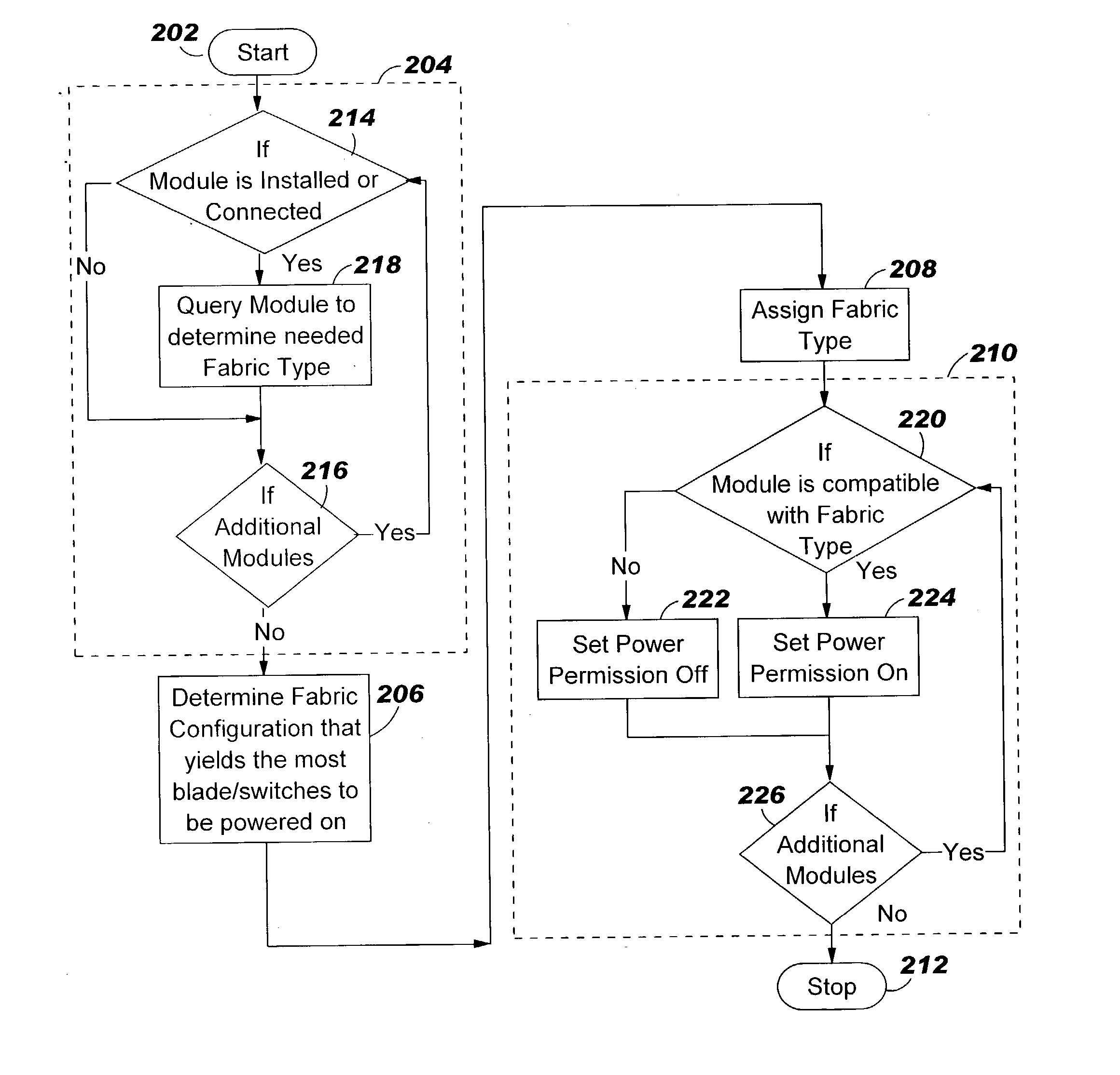
Failure to apply power at the optimum juncture could result in damage to the components and down time for the server.
Manual compatibility checking and manual cabling are unacceptable due to the likelihood of human error which could result in damage to the equipment.
In addition, operational cost is likely to be high due to cost associated with employing a service technician to perform the manual tasks enunciated above.

Method used


Image

  • Apparatus, method and program product for automatically distributing power to modules inserted in live chassis
  • Apparatus, method and program product for automatically distributing power to modules inserted in live chassis
  • Apparatus, method and program product for automatically distributing power to modules inserted in live chassis

Examples


Embodiment Construction

[0025] The description which follows presupposes knowledge of data communications network, network devices, such as servers or the like, and protocols used for transmitting information within the network. As such, general information regarding any of the enunciated items will not be given herein. Suffice it to say that background information relative to these items can be found in the literature or on the following web sites and their successors. The web sites includes:

[0026] http: / / www.pc.ibm.com / us / eserver / xseries / bladecenter_family.html?ca-=xSeries&met=ibmblade&me=A

[0027] http: / / www.carrieraccessbilling.com / telecommunications-glossary-s.a-sp

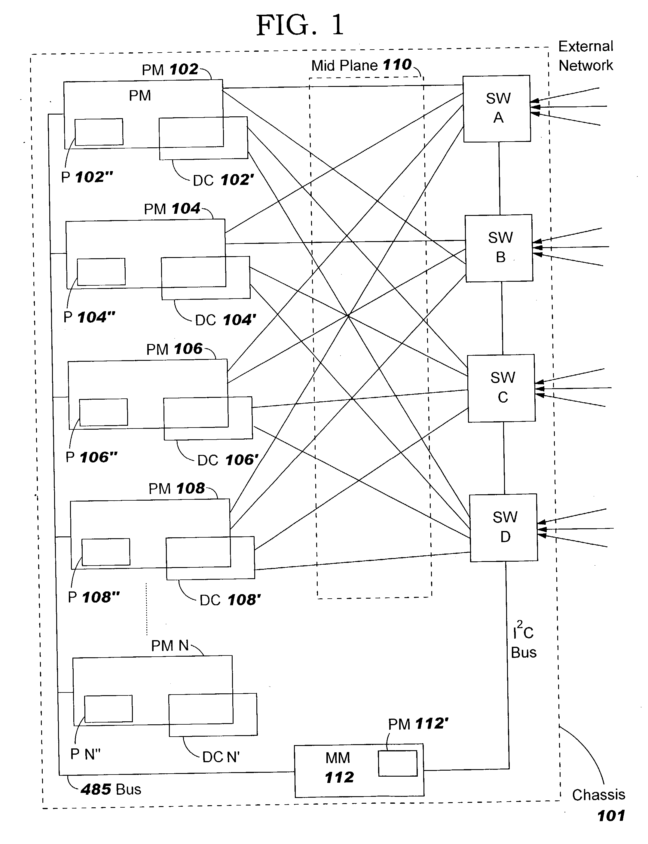
[0028] FIG. 1 shows a block diagram of server 100 which embodies the teachings of the present invention. As indicated above and described in more detail hereinafter, the present invention relates to configuration of the server and applying power to the configured subsystems so that communications between subsystems or with the external network...


PUM


Abstract

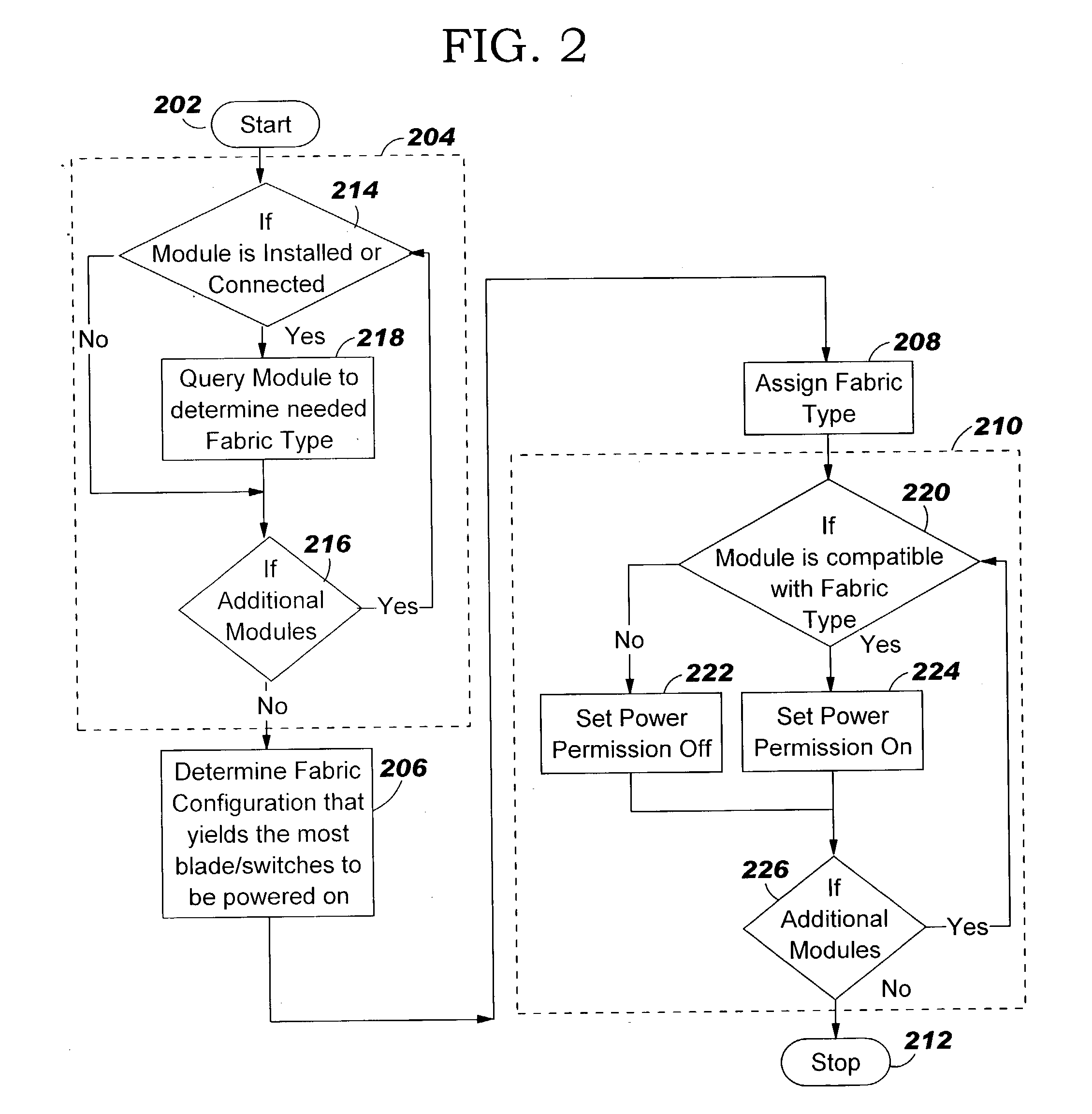
When a blade and / or interconnect device is inserted into the chassis of a powered or live server the procedure is known as hot-plugging. Before power is applied to the hot-plugged blade and / or interconnect device the fabric type of already installed blades and / or interconnect devices is correlated with fabric types of newly hot-plugged blade and / or interconnect device. Depending upon results of the correlation, power to the hot-plugged blade and / or interconnect device is allowed or denied.

Description

CROSS-REFERENCE TO RELATED PATENT APPLICATION[0001] The present invention relates to patent application Ser. No. ______ (docket RPS920020170US1) entitled "APPARATUS, METHOD AND PROGRAM PRODUCT FOR AUTOMATICALLY DISTRIBUTING POWER TO MODULES WITHIN A SERVER", by G. Dake, et al. filed concurrently herewith and assigned to the assignee of the present invention and is incorporated herein in its entirety.[0002] 1. Field of the Invention[0003] The present invention relates to communications network in general and in particular to the type of network devices termed "Servers".[0004] 2. Prior Art[0005] The use of servers as devices within communications network is well known in the art. A server is equipment that makes available file, database, printing, facsimile, communications or other services to client terminals / stations with access to the network the server serves. When the server permits client / terminal station access to external communications network it is sometimes known as a gatew...

Claims


Application Information

Patent Timeline
Patent Type & Authority Applications(United States)
IPC IPC(8): G06F13/40G06F1/26H04L12/02
CPCG06F13/4081H04L12/02
Inventor FRANKE, JEFFERY MICHAELJOHNSON, DONALD EUGENEROLLINS, MICHAEL SCOTTWOODHAM, DAVID ROBERT
Owner IBM CORP
Learn More