
Iontophoretic apparatus and method for marking of the skin

a technology of iontophoretic apparatus and skin, which is applied in the field of intradermal iontophoretic delivery of colorants for producing skin markings, can solve the problems of many of the dyes currently used, pain in needle use, fade, etc., and achieve the effect of reducing the pain perception of a person, and reducing the likelihood of human error

Inactive Publication Date: 2014-04-01
INCUBE LABS
View PDF58 Cites 3 Cited by
  • Summary
  • Abstract
  • Description
  • Claims
  • Application Information

AI Technical Summary

Benefits of technology

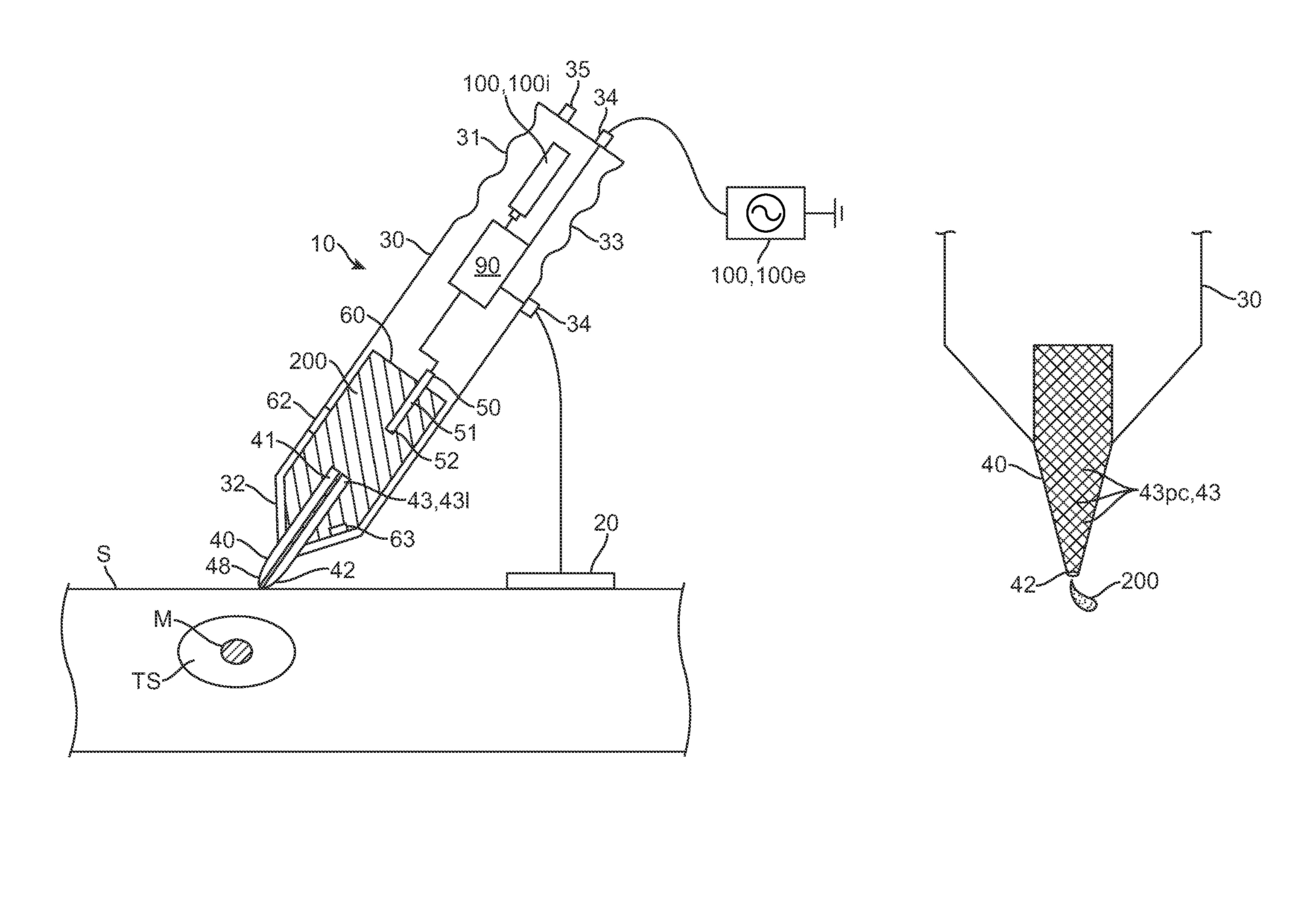
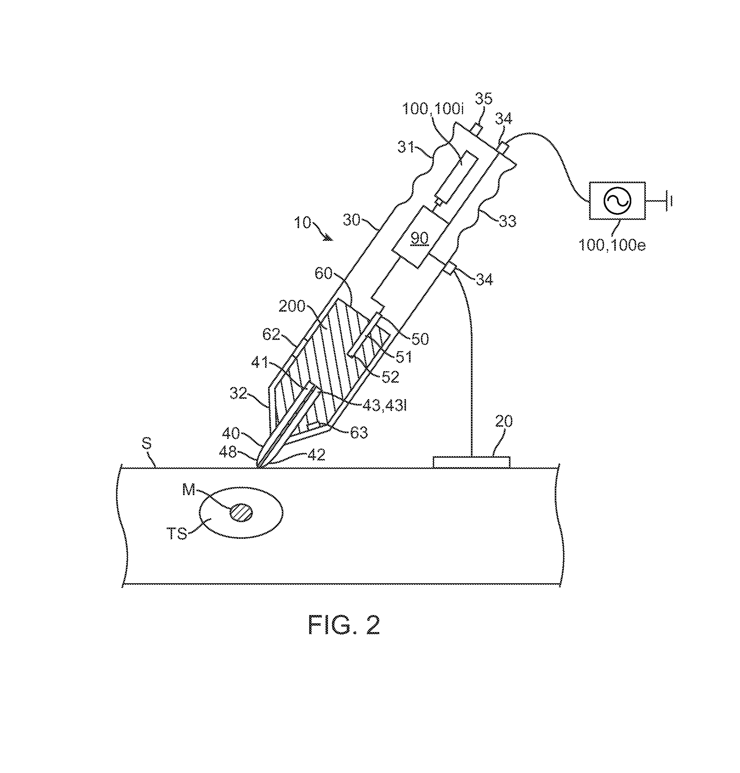
[0006]In various embodiments, the distal end or other portion of the applicator can be shaped or otherwise configured to produce a selectable current density at the interface between the applicator and the skin surface. In particular embodiments, such as those employing felt, foam or another porous material, the distal portion of the applicator can be configured as a current dispersion element which disperses or distributes current at the interface between the applicator and the skin surface by providing a plurality of conductive pathways to the skin surface. In other embodiments, the applicator can include a current concentrating element such as a hollow stylus or tube that allows for the concentration of current density at the interface between the applicator and the skin surface. The current concentrating element can be attached to the porous applicator tip so that current is more concentrated (yielding a higher current density) in one location and less concentrated (yielding a lower current density), in another location. This gradient in current densities can be used to drive varying amounts of colorant into the skin over a selected target site to produce darker and lighter areas of markings and / or drive the colorant to varying depths in the skin to produce a similar effect.
[0007]The electrode can comprise various materials including stainless steel, other conductive metals as well as carbon, for example, graphite. All or a portion of the electrode can be positioned in the reservoir and electrode is desirably positioned to minimize a voltage drop between the distal tip of the electrode and the colorant applied to the skin. In particular embodiments, the electrode can include a dielectric coating such that there is no flow of electrons between the electrode and the skin surface. Instead, current flows by means of capacitive coupling of the electrode to the colorant and the skin surface. Such embodiments minimize electrochemical degradation of the electrode and prevent unwanted migration of electrode materials into the skin.
[0010]In an exemplary embodiment of a method of using the invention to mark the skin, the apparatus is coupled to a power source and a return electrode which is positioned on the skin near the target site for marking. The user then places the applicator tip on the target site for marking and may keep the tip stationary or may move the tip across the surface of the skin. Colorant is delivered from the tip to the skin surface using the felt or other porous tip of the applicator. Current is then delivered from the electrode to ionize the colorant and transport the colorant a selected depth into the skin using an electromotive force from the voltage associated with the current. The colorant then produces a marking at the delivered location in the skin from the pigment. Typically, the driving force is an iontophoretic driving force whereby the charged ionized compounds in the colorant are repelled by a like charge from the electrode and migrate into the skin as a result. The colorant can comprise an ionizable pigment such as various iron containing compounds. The colorant may also comprise chargeable nano-particles such as hematite particles which contain a pigment compound. The current can include alternating or direct current as well as combinations thereof. In specific embodiments, the delivered current can comprise a DC component and an AC component. The AC component can be configured to discharge and thus breakdown the build-up of capacitive charge in skin tissue which may impede the migration of colorant into the skin. Also in various embodiments, the current can be modulated (e.g., by changing the waveform, frequency, amplitude, etc) to control the penetration depth of colorant into the skin as well as reduce the pain perception of a person receiving a marking.
[0011]The markings produced by the apparatus can be used for decorative, medical and identification purposes. For the latter two applications, magnetic colorants such as those containing ferrite materials can be used such that they can be detected and read trans-dermally by a magnetic reading device such as a hand held magnetic reader. In use, such embodiments allow a medical practitioner to pre-operatively mark a limb or other portion of the body to be operated on with magnetically readable marking indicating that is the limb or body portion to be operated on. Then immediately prior to surgery, the surgeon would scan the limb with the magnetic reading device to ensure that the limb is the correct limb. Theses and related embodiments serve to reduce the likelihood of error of the wrong limb or other body part being operated on. In related embodiments, the contra-lateral limb which is not be to be operated on can be intradermally marked with readable indicia indicating that it is not the limb to be operated on. In use, such embodiments provide two levels of quality assurance to ensure the correct limb or other intended portion of the anatomy is operated on. That is, before a limb can be operated on, the surgeon must verify to make sure that it is the correct limb and also that it is not the incorrect limb. Such embodiments are particularly useful for reducing the likelihood of human error during a surgical or other medical procedure in operating on the wrong limb or other portion of the anatomy.

Problems solved by technology

However, use of needles is a painful process which has various associated health risks including infection (e.g., from contaminated needles) allergic and phototoxic reactions.
Also, many of the dyes currently used can fade over time.

Method used


Image

  • Iontophoretic apparatus and method for marking of the skin
  • Iontophoretic apparatus and method for marking of the skin
  • Iontophoretic apparatus and method for marking of the skin

Examples


Embodiment Construction

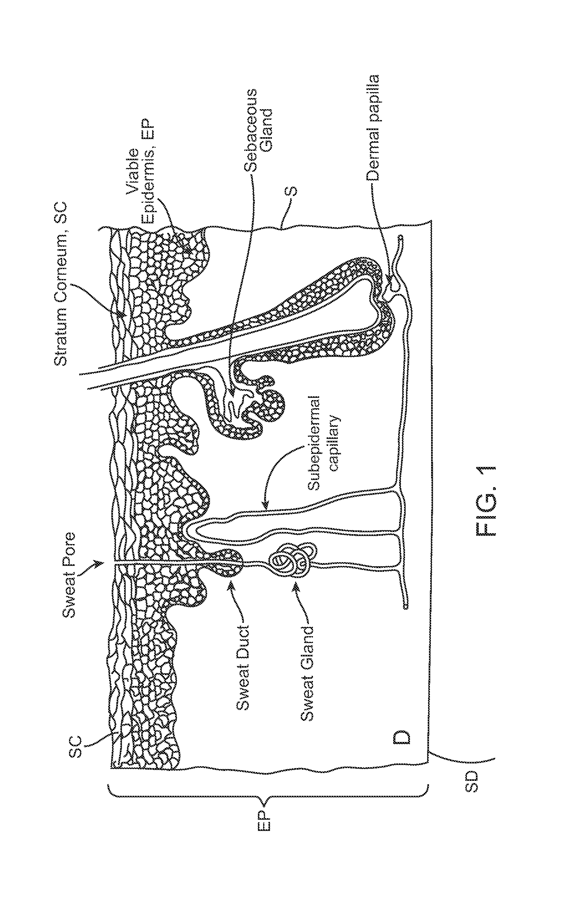
[0020]Many embodiments described herein provide a system and method for intradermal iontophoretic delivery of colorants to produce markings in the skin. A brief explanation will be provided for these terms as well as the anatomy of the skin. Referring now to FIG. 1, the layers of the skin include the epidermis EP, dermis D and subdermis SD. The upper most layer of the epidermis includes the stratum corneum SC a dead layer of skin (having a thickness of about 10 to 40 μm) and the viable epidermis EP. The term intradermal refers to the delivery of a substance such as a colorant into the skin S including one or both of the epidermal E and dermal D layers.

[0021]Iontophoresis is a non-invasive method of propelling high concentrations of a charged substance, known as the active agent, into or through the skin by repulsive electromotive force using a small electrical charge. The charge is applied by an electrical power source to an active electrode assembly placed on the skin which contain...


PUM


Abstract

Embodiments provide apparatus and methods for producing markings in the skin. One embodiment provides an apparatus for marking the skin comprising a housing and reservoir for storing a skin colorant. An electrode is positioned within the housing so as to be electrically coupled to the colorant in the reservoir and is configured to be coupled to a current source and return electrode. A colorant applicator having at least one fluid pathway is coupled to a housing distal end. The applicator proximal end is positioned such that the fluid pathway is coupled with the reservoir. The applicator distal end applies colorant to the skin surface through the fluid pathway as the applicator is moved across the skin. The electrode delivers current from the current source to the skin to transport charged pigment elements of the colorant into the skin using an electromotive driving force to produce a marking in the skin.

Description

FIELD OF THE INVENTION[0001]Embodiments described herein relate to intradermal delivery of colorants for producing skin markings. More specifically, embodiments described herein relate to intradermal iontophoretic delivery of colorants for producing skin markings.BACKGROUND[0002]The skin consist of three main layers: the epidermis (the outermost layer), the dermis and subcutaneous tissue. Tattooing or marking of the skin involves embedding dyes into one or both of the epidermal or dermal layers. Typically, this is done using needles. However, use of needles is a painful process which has various associated health risks including infection (e.g., from contaminated needles) allergic and phototoxic reactions. Also, many of the dyes currently used can fade over time. Thus, there is need in the art for improved tattooing methods of the skin.BRIEF SUMMARY[0003]Embodiments described herein provide methods for using electrically based intradermal delivery methods such as intradermal iontoph...

Claims


Application Information

Patent Timeline
Patent Type & Authority Patents(United States)
IPC IPC(8): A61B17/00
CPCA61N1/325A61N1/328A61N1/303A61N1/044A61N1/0428A61M37/0084A61N1/0448A61N1/0436A61M2037/0007A61M2210/04
Inventor IMRAN, MIR
Owner INCUBE LABS
Learn More