Method of securing cables to a wind turbine blade

a technology of wind turbine blade and cable, which is applied in the direction of wind turbines, wind turbines, machines/engines, etc., can solve the problems of increasing the cost and weight of the blade, affecting the installation process, so as to facilitate the cable installation process and relieve any tension

Active Publication Date: 2022-01-18
VESTAS WIND SYST AS
View PDF11 Cites 0 Cited by
  • Summary
  • Abstract
  • Description
  • Claims
  • Application Information

AI Technical Summary

Benefits of technology

[0007]This aspect of the invention provides a particularly quick and advantageous method of securing a cable to a wind turbine blade. By pre-assembling the cable assembly, the correct amount of slack may be incorporated into the cable offline. The cable assembly can then be installed quickly and efficiently during the blade fabrication process. Furthermore, the likelihood of human error during the fabrication process is reduced.
[0010]The tension cord is an advantageous addition to the cable assembly, in that it may prevent the cable from being stretched or strained during transportation, installation and use. As the tension cord is preferably substantially inextensible and shorter than the length of the cables between adjacent mounts, the tension cord may be pulled taut during installation of the cable assembly without any strain being placed upon the cable. Pulling the tension cable taut results in the mounts being arranged with suitable predefined spacings between mounts on the blade surface, whilst a predetermined amount of slack is ensured in the cable between the mounts.
[0012]If desirable, the method may comprise detaching the tension cord from the mounts and / or severing the tension cord between adjacent mounts after attaching the mounts to the surface of the blade. This relieves any tension on the mounts once the mounts have been attached to the blade. However, in certain embodiments it may not be required to detach or sever the tension cord, and it may remain in place after installation of the cable assembly.
[0013]The method optionally comprises providing a template on the surface of the blade indicating a plurality of mounting positions respectively for the plurality of mounts. The template serves as a useful guide for indicating the mounting positions for the mounts and may facilitate the cable installation process.
[0014]In certain embodiments, the provision of a template may avoid the need for a tension cord. For example, if the tension cord is omitted, then the method may comprise pre-attaching the mounts to the cable with spacings between mounts that are greater than an intended spacing between the mounts when the mounts are attached to the blade. Thereafter, during installation of the cable assembly, the method may comprise providing a template on the surface of the blade indicating a plurality of intended mounting positions respectively for the plurality of mounts, wherein the spacing between adjacent mounting positions is less that than the length of cable between said adjacent mounts.
[0017]The pre-assembled cable assembly may be coiled on a cable drum. This provides a convenient means of storing and transporting the cable assembly. It also facilitates the installation process, which may therefore involve uncoiling the cable assembly across the surface of the blade.

Problems solved by technology

It is important to ensure an appropriate amount of slack when installing the cables: too little slack may leave the cables susceptible to damage, whilst too much slack may result in the cables flapping inside the blade, which may also result in damage to the cables or to other components inside the blade.
Too much slack also unnecessarily increases the length of cable inside the blade, leading to an increased cost and weight of the blade.
Ensuring a suitable amount of slack in the cable can be complicated and time-consuming during the blade manufacturing process, and relies upon the cable installer accurately measuring lengths of cable during installation.
As well as being complicated, this also introduces a risk of human error during the installation process.

Method used


Image

  • Method of securing cables to a wind turbine blade
  • Method of securing cables to a wind turbine blade
  • Method of securing cables to a wind turbine blade

Examples


Embodiment Construction

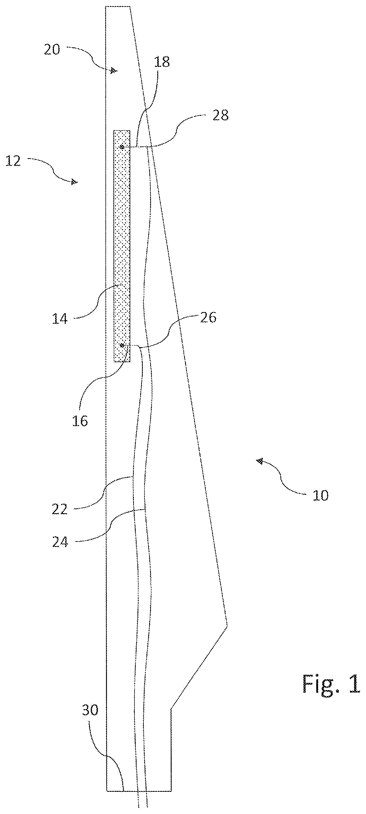
[0030]FIG. 1 shows a wind turbine blade half-shell 10 incorporating an anti-ice system 12. The anti-ice system 12 comprises a plurality of electro-thermal heating elements 14, one of which is shown in FIG. 1. Each heating element 14 is configured to warm an area of an outer surface (not shown) of the blade to prevent ice from forming in the heated area.

[0031]The electro-thermal heating element 14 is embedded within the laminate structure of the half-shell 10. Electrical connectors 16, 18 connect to the electro-thermal heating element 14 and extend from the embedded heating element 14 to an inner surface 20 of the half-shell 10. A pair of electrical cables 22, 24 is provided inside the blade for supplying power to the heating element 14. A first end 26, 28 of each cable 22, 24 is connected to a respective electrode 16, 18.

[0032]When the wind turbine blade is installed on a wind turbine hub, a second end (not shown) of each cable 22, 24 is connected to a power distribution box (not sh...


PUM


Abstract

A method of securing a cable (22) to a wind turbine blade is described. The method involves providing a pre-assembled cable assembly (34) comprising a cable (22) and a plurality of mounts (40a-e) pre-attached to the cable (22) at intervals along the length of the cable (22). The plurality of mounts (40a-e) is attached to a surface (20) of a wind turbine blade such that the mounts (40a-e) are spaced apart along the surface (20) of the blade. The spacing between adjacent mounts (40a-e) when the mounts (40a-e) are attached to the blade is less than the length of the cable (22) between said adjacent mounts (40a-e) such that a predetermined amount of slack is provided in the cable (22) between said adjacent mounts (40a-e). A pre-assembled cable assembly for use in the method is also described together with a method of assembling the cable assembly.

Description

TECHNICAL FIELD[0001]The present invention relates to a method of securing cables to a wind turbine blade and to an associated cable assembly.BACKGROUND[0002]Modern wind turbine blades may incorporate a variety of electrical components within the blade. Such components include heating elements for use in de-icing or anti-icing systems, illumination elements and sensors, for example. These components may be connected to the electrical system of the wind turbine by cables that extend inside the blade. The cables are typically secured to the inner surface of the blade shell.[0003]When securing the cables to the blade, it is desirable to include some slack in the cables to prevent the cables from stretching or otherwise becoming strained or damaged during flexing of the blade in use. It is important to ensure an appropriate amount of slack when installing the cables: too little slack may leave the cables susceptible to damage, whilst too much slack may result in the cables flapping insi...

Claims


Application Information

Patent Timeline
Patent Type & Authority Patents(United States)
IPC IPC(8): F03D13/00F03D1/06
CPCF03D13/00F03D1/0675F03D80/85Y02E10/72
Inventor SPANDLEY, LUKEBADGER, PAULBUGGY, STEPHEN
Owner VESTAS WIND SYST AS
Why Eureka
Try Eureka