Lighting apparatus

a technology of light-emitting devices and light-emitting devices, which is applied in the direction of fixed installation, lighting and heating devices, and support devices for lighting and heating, etc., can solve the problems of affecting the design of the shade, the structure became too complicated, and the apparatus is not easy to handle, so as to achieve the effect of easy attachment and detachment, less expensive structure and easy shade rotation

Inactive Publication Date: 2002-04-23
TWINBIRD CORP
View PDF3 Cites 3 Cited by
  • Summary
  • Abstract
  • Description
  • Claims
  • Application Information

AI Technical Summary

Benefits of technology

to provide a lighting apparatus which realizes an easier attachment and detachment as well as an easier rotation of the shade with a simple and less expensive structure.
It is another object of the invention to provide a lighting apparatus with an enhanced degree of freedom in designing the same.
According to the first aspect of the invention, the shade can be easily mounted to the head through the engagement of the former to the latter by fitting the protrusions formed on the shade or the head into the grooves formed on the head or the shade.
According to the second aspect of the invention, when a user rotates the shade around the axis of the head, the protrusions or grooves formed on the shade are slidable within the arc-shaped portions along the grooves or protrusions formed on the head, so that the shade is easily rotated around the axis, thereby easily adjusting the direction of light.
In addition, according to a third aspect of the invention, there is provided a lighting apparatus with the structure of foregoing aspects, wherein said head and shade are each formed with at least one pair of the protrusions or the grooves. Thus, the shade can be fixedly mounted to the head without wobbling.

Problems solved by technology

According to the structure disclosed by the former prior art, however, as the lighting tool which is rotatable relative to the arm consisted of the shade, the socket and the lamp, the tool was so heavy that it required other mechanisms such as a tightening mechanism or a stopper mechanism for tightening or making the rotating mechanism stationary, and thus, the structure became too complicated.
Besides, to move the shade which was once made stationary, it was necessary to relax the tightening mechanism or to release the stopper mechanism, thereby resulting in a nuisance in handling the apparatus.
Furthermore, as the socket and the lamp were mounted to the shade, there was resulted a certain constraint in designing the shade.
According to the structure of the latter prior art, whilst the weight of the movable part became smaller, it was necessary to attach the shade, using the fastening cover which is separate from the shade, so that not only the attaching and detaching works of the shade were a nuisance, but also the increased costs were resulted.

Method used


Image

  • Lighting apparatus
  • Lighting apparatus
  • Lighting apparatus

Examples


Embodiment Construction

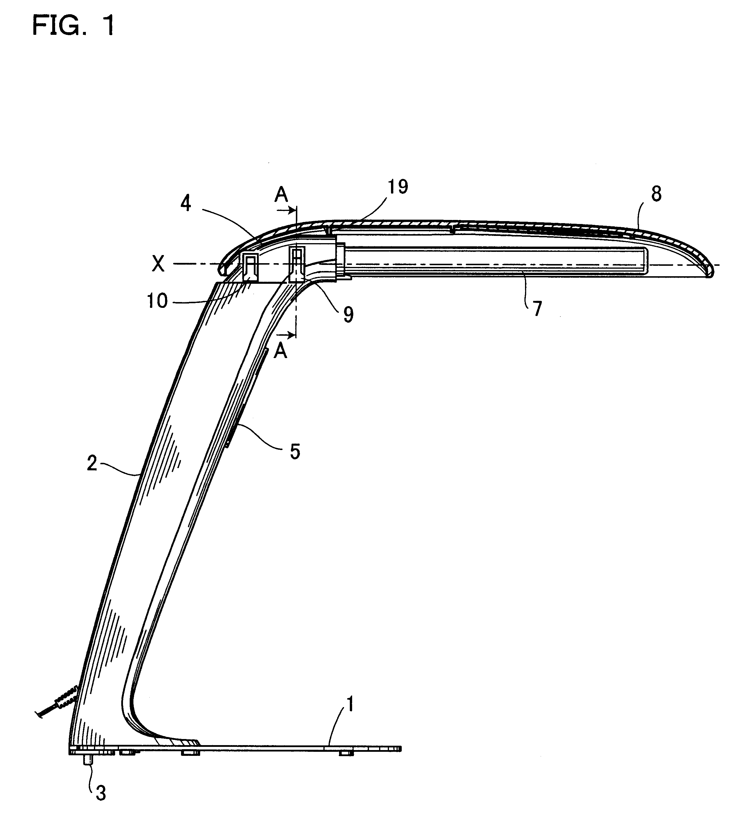
Hereinafter are described preferred embodiments of the present invention with reference to FIGS. 1 through 3.

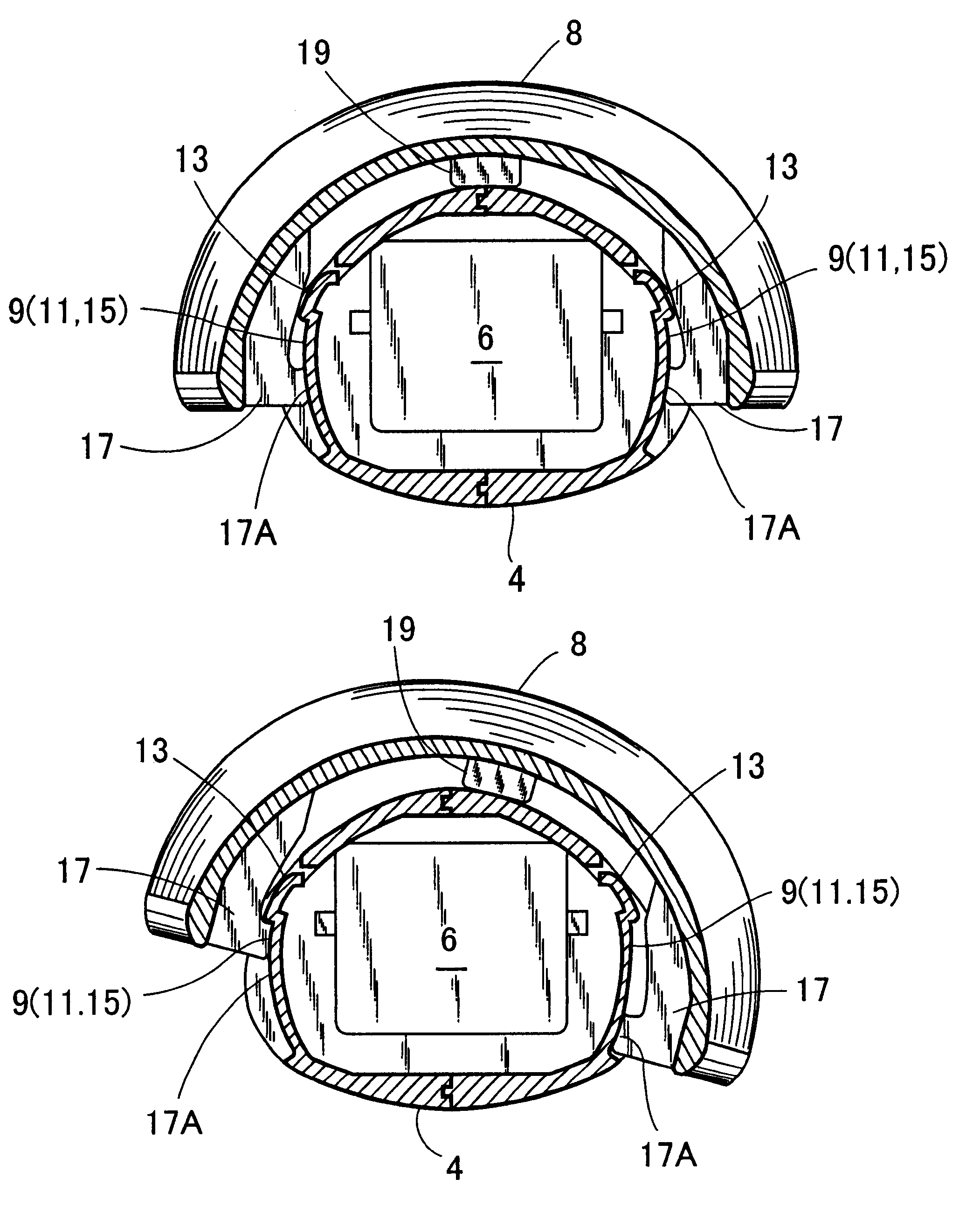
Reference numeral 1 designates a metallic plate-like base, said base 1 having an end to which is mounted a post 2. Below the post 2 is provided a safety switch 3 protruding downwardly of the base 1, while above the post 2 is integrally provided a head 4. The post 2 comprises a lighting switch 5. The head 4 is provided by bending an upper portion of the post 2 so that it extends along a virtual horizontal axis X, having a socket 6 for connecting a fluorescent light bulb on its end. The fluorescent light bulb 7 is removably mounted to the socket 6 of the head 4 in a manner that the longitudinal direction of the fluorescent light bulb 7 may coincide with that of the head 4. A shade 8 is removably mounted so as to cover the head 4 and the fluorescent light bulb 7.

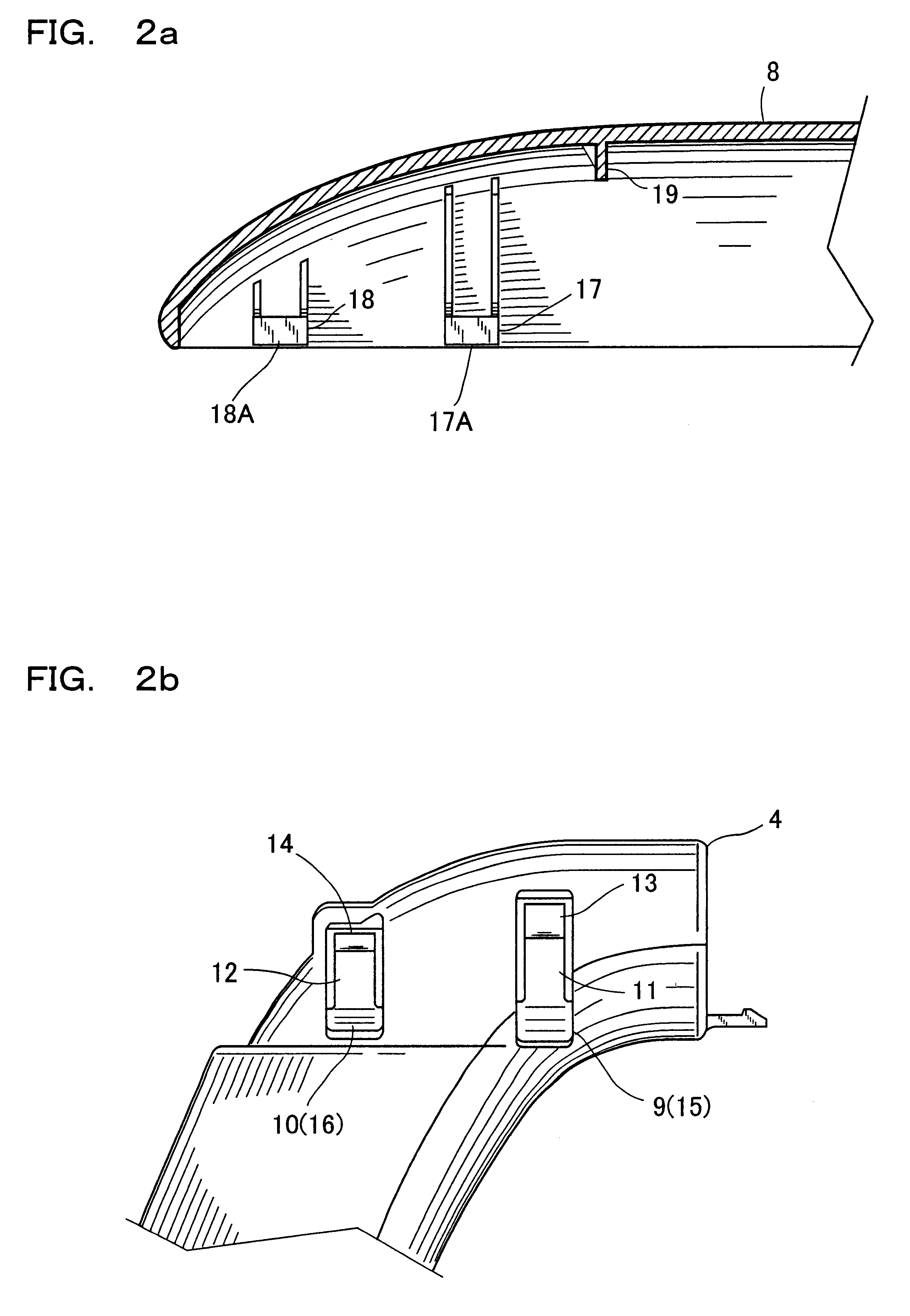
An external surface of the head 4 is formed with concavities or grooves 9 and 10 provided around the virtual axis X. T...


PUM


Abstract

A lighting apparatus which enables a shade to be easily attached, detached and rotated with a simple structure and an enhanced degree of freedom in design. Grooves 9,10 defining arc-shaped portions 15,16, respectively, are formed around an axis of a head 4, to which is mounted a fluorescent light bulb 7. A shade 8 which is formed with protrusions 17, 18 opposite to the grooves 9, 10 is mounted to the head 4 so as to cover the fluorescent light bulb 7. By pressing the protrusions 17, 18 of the shade 8 into the grooves 9, 10 of the head 4, the shade 8 can be very easily mounted to the head 4. By lifting up the shade 8 from the head 4, the shade 8 can be very easily removed from the head 4. In addition, the shade 8 can be rotated by allowing the protrusions 17, 18 formed on the shade 8 to slide along the arc-shaped portions 15, 16. As such shade 8 allows a simple integral structure, degree of freedom in designing a lighting apparatus can be enhanced.

Description

a) Field of the InventionThe present invention relates to a lighting apparatus, particularly to a mounting structure of a shade for use with an electric table lamp.b) Prior ArtConventional lighting apparatus, particularly a conventional electric table lamp, is disclosed for example in Japanese Utility Model Un-Examined Publication No.6-50130 and Japanese Utility Model Examined Publication No.7-51691. The Publication No. 6-50130 discloses an electric lamp which comprises: a shade; an arm; and a lamp mounted to the shade, said shade having one end rotatably mounted to an upper end of said arm through a rotating mechanism. In this prior art, a socket and the lamp are attached to the shade, thus enabling the adjustment of the lighting direction by the rotation of the shade. The latter prior art or the Publication No. 7-51691 discloses another table lamp which comprises: an arm; an attachment plate mounted to the arm; a straight-tube-type lamp; and a socket provided on the attachment pla...

Claims


Application Information

Patent Timeline
Patent Type & Authority Patents(United States)
IPC IPC(8): F21V17/02F21S6/00F21V17/00F21V17/16F21Y103/00
CPCF21S6/003F21V17/164F21V17/02F21Y2103/00
Inventor MARUYAMA, KANAMEHONDA, TAKASHITANIGUCHI, SHUICHIHORI, MASAHIKO
Owner TWINBIRD CORP
Why Eureka
Try Eureka