Heat of compression dryer

a dryer and heat technology, applied in the direction of chemistry apparatus and processes, separation processes, dispersed particle separation, etc., can solve the problem that the dryer that regenerates at the outlet can provide very limited performance, and achieve the effect of improving the heat of the dryer

Inactive Publication Date: 2002-04-23
HENDERSON ENG CO INC
View PDF27 Cites 94 Cited by
  • Summary
  • Abstract
  • Description
  • Claims
  • Application Information

AI Technical Summary

Benefits of technology

A general object of the present invention is to

Problems solved by technology

Many compressors have low discharge temperatures and thus the dryer tha

Method used


Image

  • Heat of compression dryer
  • Heat of compression dryer
  • Heat of compression dryer

Examples


Embodiment Construction

While the invention may be susceptible to embodiment in different forms, there is shown in the drawings, and herein will be described in detail, a specific embodiment with the understanding that the present disclosure is to be considered an exemplification of the principles of the invention, and is not intended to limit the invention to that as illustrated and described herein.

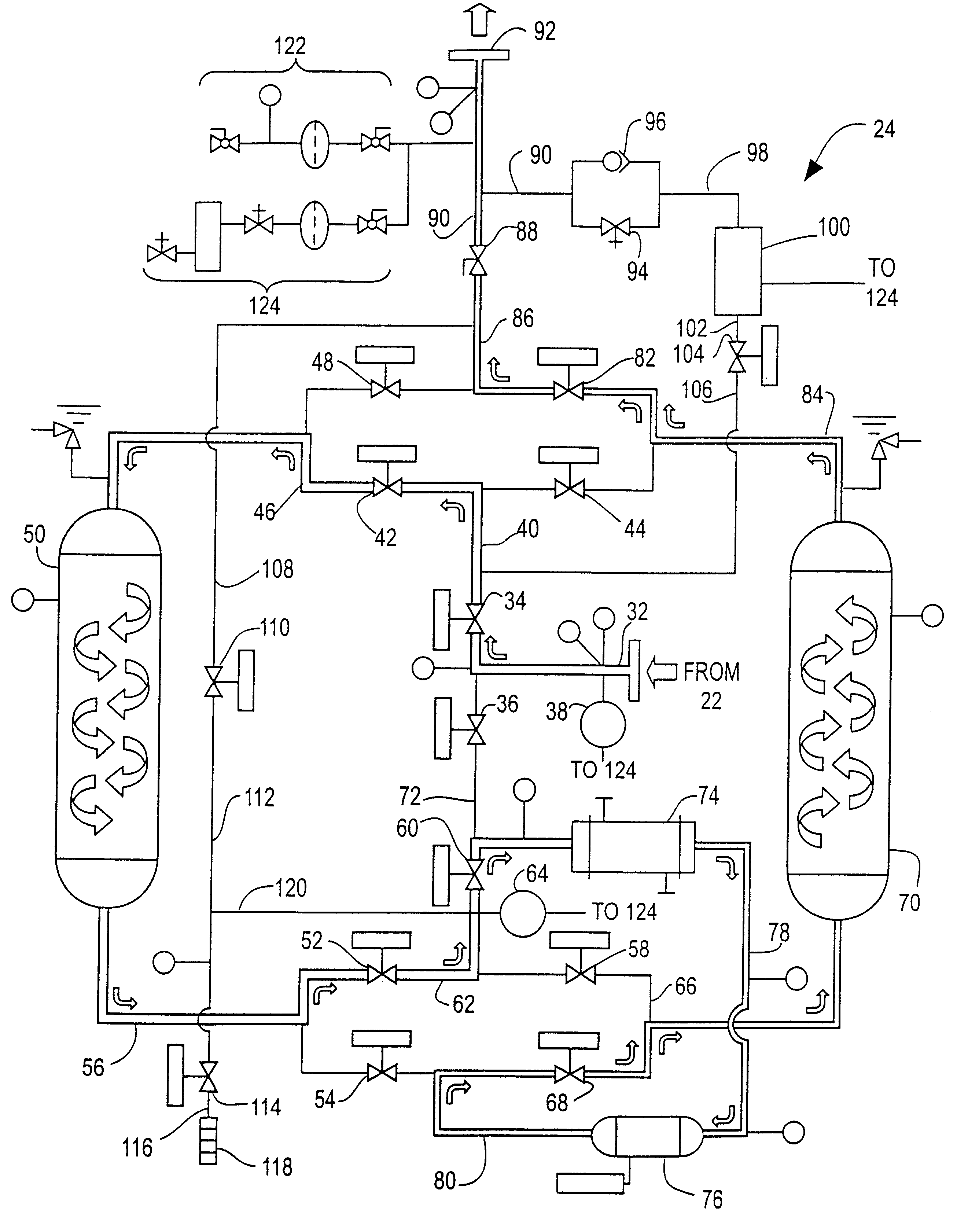
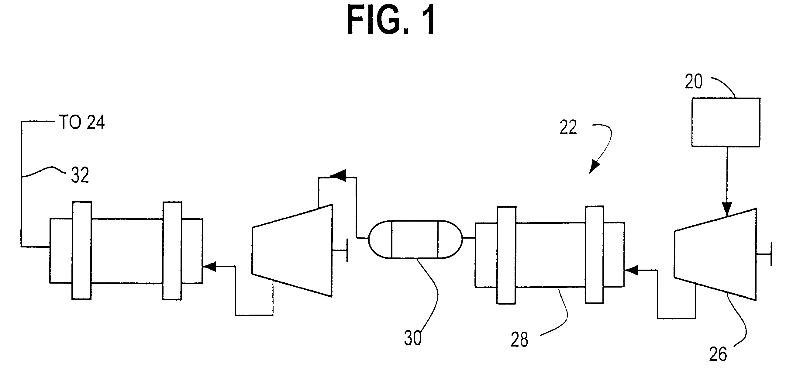
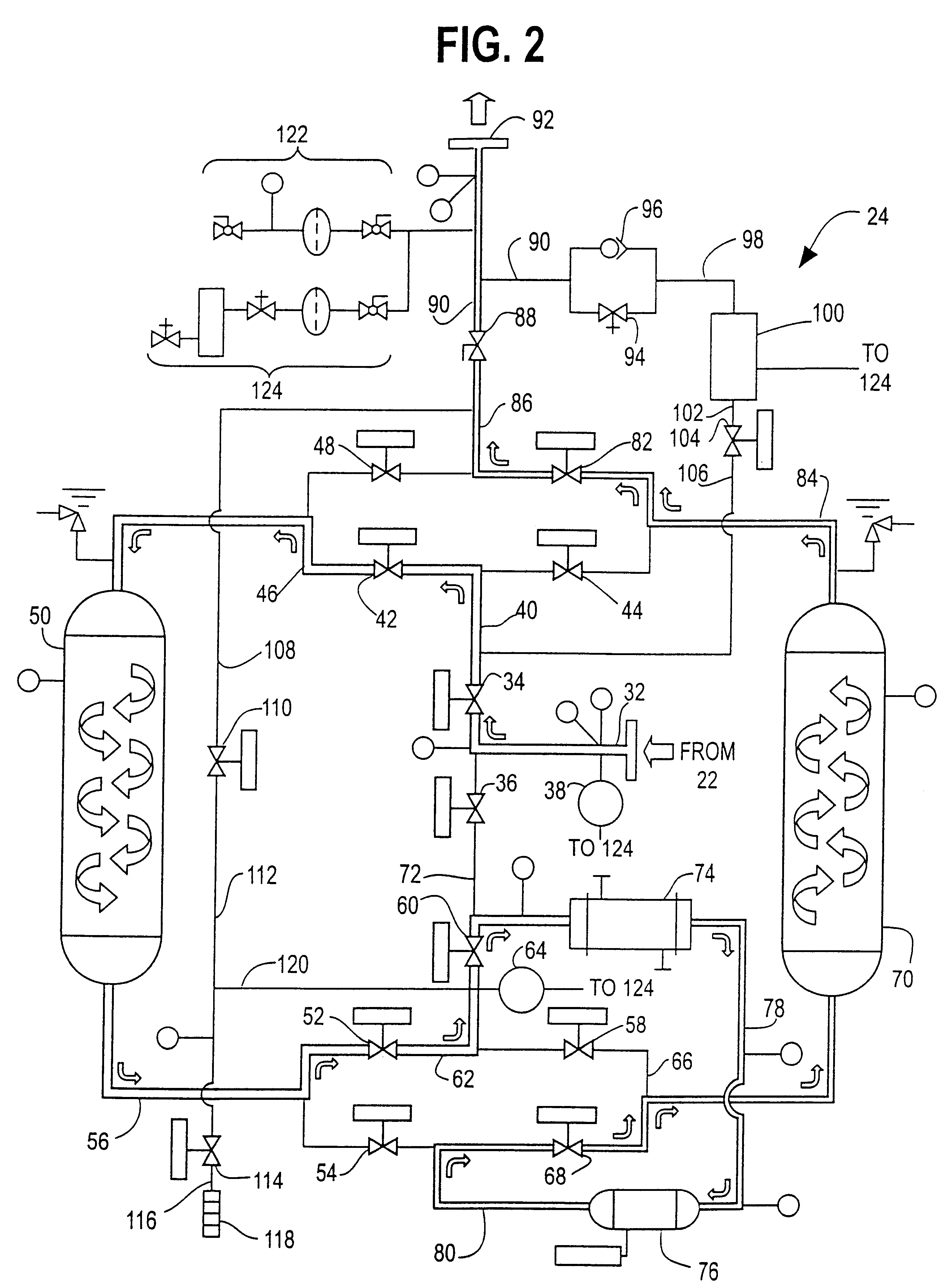
The present invention provides a novel regenerative compressed dryer system for drying a gas, such as air. The system includes a compressor 22 and a dryer 24 which have been combined to enhance the performance of the dryer 24 versus prior art dryers.

The compressor 22 may be a multi-stage compressor. Each stage in the compressor 22 includes a compression stage 26, a heat exchanger 28 and a moisture separator 30 or other like separator. The inlet of the compressor 22 is connected to a source 20 of gas. The outlet of the compressor 22 is connected to the inlet of the dryer 24. The dryer 24 may also be located bet...


PUM


Abstract

A system for drying a gas includes a source of gas, a compressor connected to the source, and a heat of compression dryer connected to the compressor. The dryer includes a first tower and a second tower, each tower containing desiccant material therein. Temperature monitors are provided at the inlet of the dryer and at the outlet of the towers. Temperature readings from the temperature monitors are communicated to a controller which determines a suitable mode in which the dryer is to be placed.

Description

This invention is generally directed to an improved heat of compression dryer which provides performance under virtually any operating condition.Today, dryers are designed to operate at the outlet of the compressor. With a heat of compression type dryer, the discharge temperature of the air at the outlet of the compressor is a critical item that determines the efficiency of the dryer. Many compressors have low discharge temperatures and thus the dryer that regenerates at the outlet is able to provide very limited performance.The present invention overcomes or minimizes the deficiencies of the prior art by providing a novel dryer having a controller and a communication structure which enables the dryer to be placed in predetermined modes to maximize the efficiency of the dryer. Other features and advantages will become apparent upon a reading of the attached specification, in combination with a study of the drawings.OBJECTS AND SUMMARY OF THE INVENTIONA general object of the present ...

Claims


Application Information

Patent Timeline
IPC IPC(8): B01D53/26B01D53/04
CPCB01D53/0454B01D53/261B01D2259/402
Inventor HENDERSON, CHARLES A.HENDERSON, TERRY D.
Owner HENDERSON ENG CO INC
Why Eureka
Try Eureka