Portable transmitter for vehicle key system

a key system and transmitter technology, applied in the field of keys, can solve the problems of increasing the size of the keyless transmitter and inconvenient carrying for users

Inactive Publication Date: 2002-04-23
MITSUBISHI ELECTRIC CORP
View PDF11 Cites 48 Cited by
  • Summary
  • Abstract
  • Description
  • Claims
  • Application Information

AI Technical Summary

Problems solved by technology

As above described, in the conventional keyless entry system or key system, the sender switch 101 or a plurality of function switches, other than the fingerprint sensor, were required to provide on the side of the keyless transmitter, as shown in FIGS. 9A and 9B, thereby resulting in a problem that the keyless transmitter is increased in size and is inconvenient for the user to carry it.

Method used


Image

  • Portable transmitter for vehicle key system
  • Portable transmitter for vehicle key system
  • Portable transmitter for vehicle key system

Examples


embodiment 1

One embodiment of this invention will be described below with reference to the drawings. A basic configuration of a key system according to this invention is substantially the same as the conventional keyless entry system as shown in FIG. 8, and is not described in detail. However, the functional units for performing various functions which are connected to a control device 9 include an engine start / stop control unit 55 for starting or stopping the engine from the outside of the vehicle, and a trunk lid open unit 57 for opening the trunk lid.

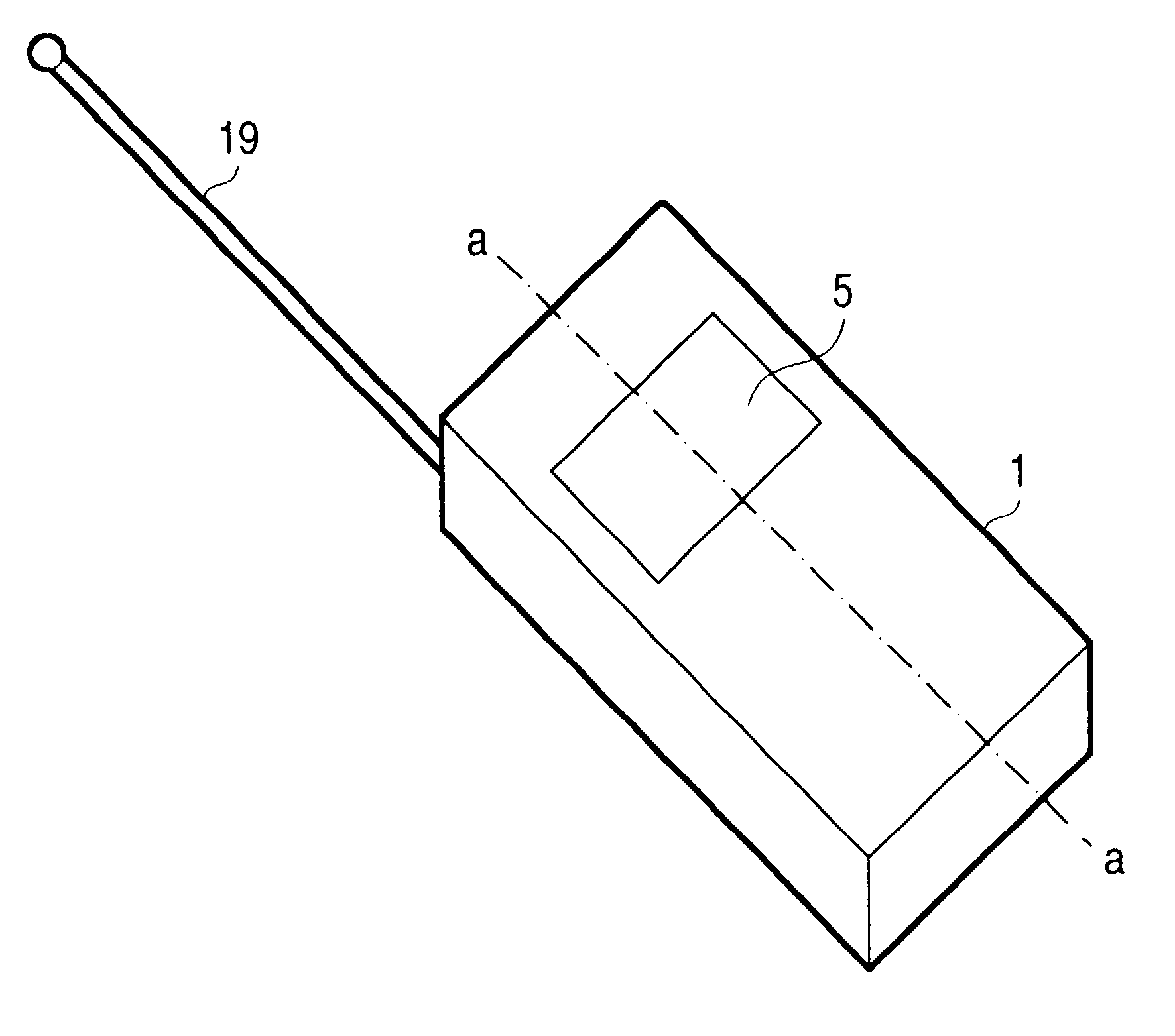
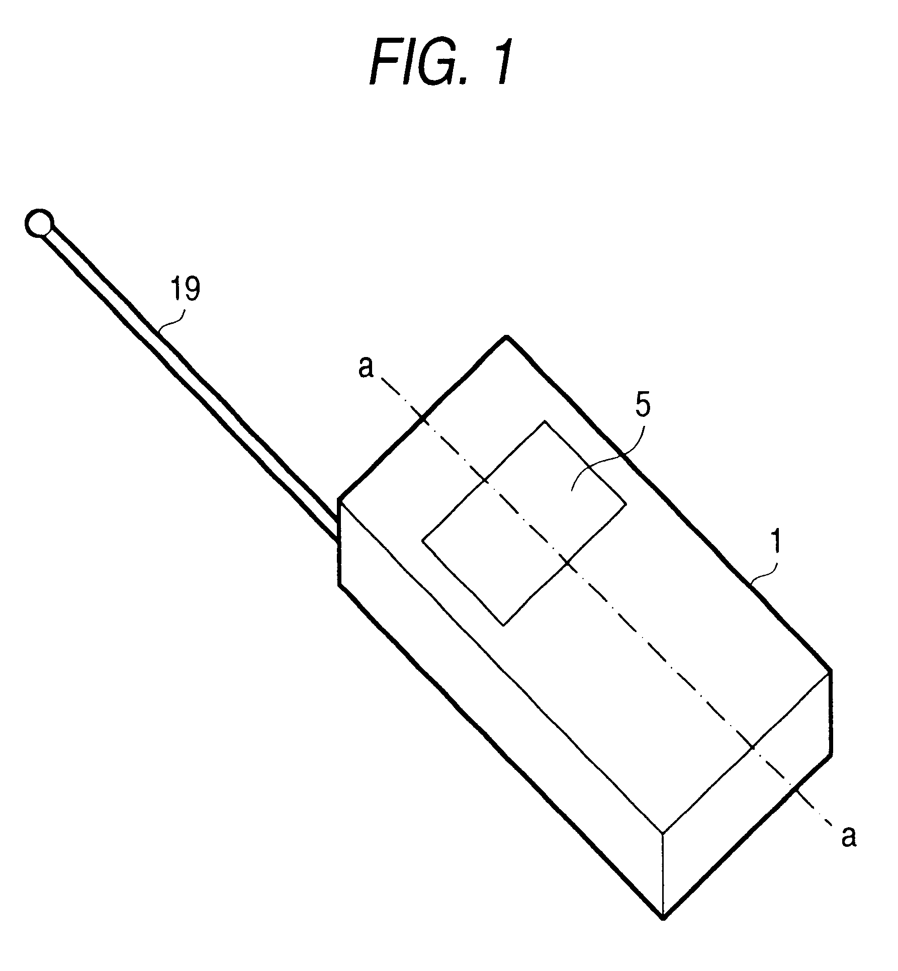
FIG. 1 shows one embodiment of a keyless transmitter 1 according to this invention. The keyless transmitter 1 has a fingerprint sensor 5 and an antenna 19, as above described, and contains a sending component 17 for sending the fingerprint data detected by this fingerprint sensor 5. This antenna 19 may be a so-called rod antenna, as shown in FIG. 1, or may be contained within the keyless transmitter 1.

The fingerprint sensor 5 as shown in FIG. 1 ...

embodiment 2

While the fingerprint data is transmitted by turning on the sender switch 101 in one embodiment of this invention as above described, it can be understood that the kind of command signal to be transmitted with the fingerprint data may be determined in accordance with the number of depressing the fingerprint sensor 5 to turn on the sender switch 101, to operate various functions.

For example, an embodiment 2 can be configured to send a door lock command signal by depressing once, an engine start command signal by depressing twice, an open command signal of trunk lid by depressing three times, a door unlock command signal by depressing four times, and an engine stop command signal by depressing five times.

With such a configuration, various kinds of command signals can be transmitted by manipulating one sender switch 101, so that the keyless transmitter can be reduced in size while the keyless system has a variety of functions.

While in the embodiment 2 of the invention as above describe...

embodiment 3

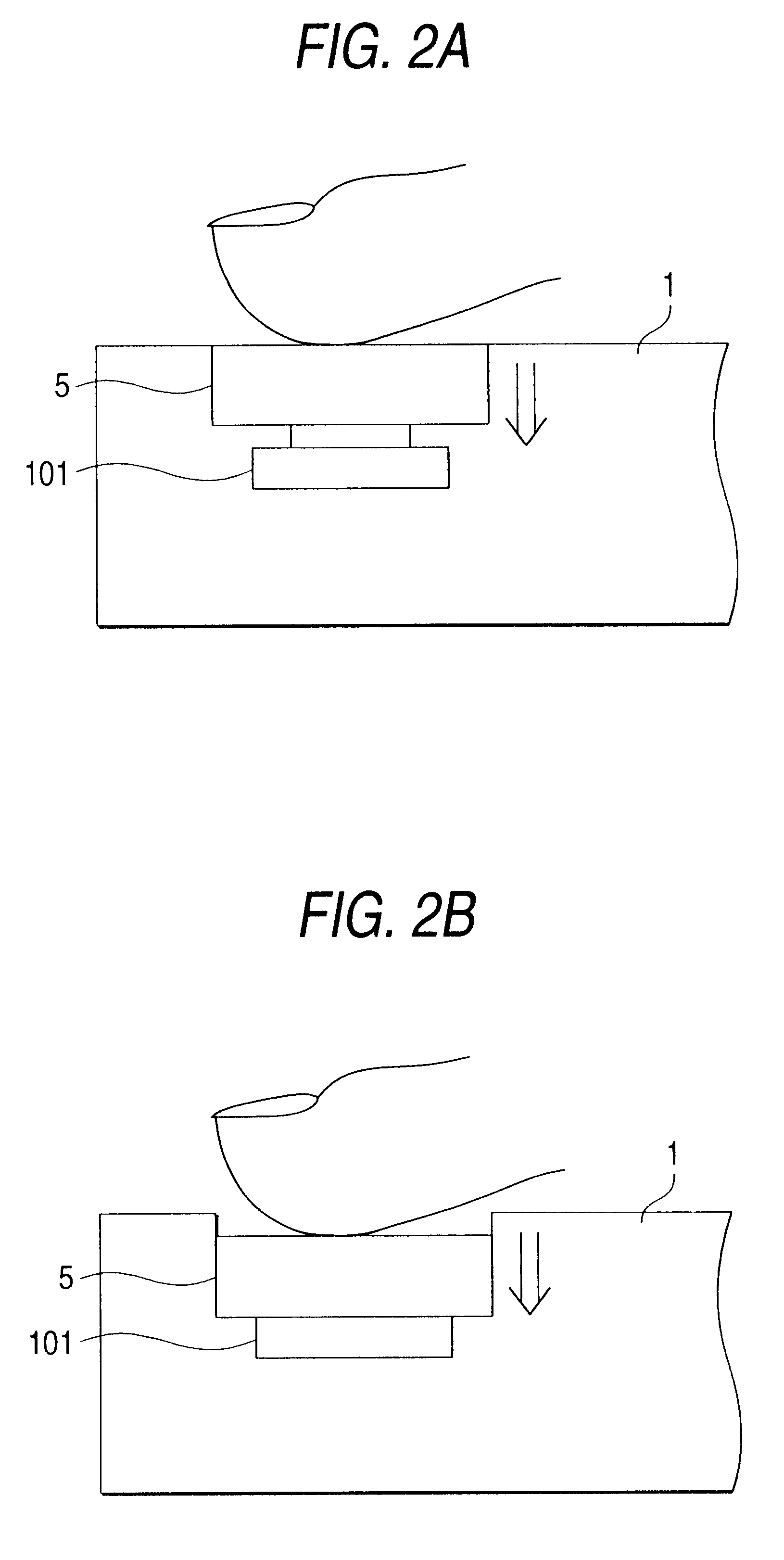
An embodiment 3 will be described below. FIGS. 4A and 4B show a keyless portable transmitter 1 according to the embodiment 3 of this invention, wherein the fingerprint sensor 5 is configured to slide upward in the figure as indicated by the arrow.

The use condition of the keyless transmitter 1 as thus configured will be described below. Firstly, the user places one's finger on the fingerprint sensor 5 of the keyless transmitter 1. Thereafter, the user slides the fingerprint sensor 5 upward in the figure to turn on the sender switch 101, so that the sending component 17 can send the fingerprint data.

In the embodiment 3 as above described, the user performs the operation of sliding the fingerprint sensor 5 to send the fingerprint data, whereby the accidental transmission against the user's will can be efficiently avoided, and the keyless transmitter can be reduced in size to enhance the portability.


PUM


Abstract

A portable transmitter of vehicle key system comprising a fingerprint detecting portion for detecting the user's fingerprint, a sending component for sending the fingerprint data from this fingerprint detecting portion, and a sender switch for triggering the transmission of fingerprint data from this sending component, this sender switch and the fingerprint detecting portion being disposed integrally, whereby the sender switch is activated in accordance with the user operating the fingerprint detecting portion.

Description

1. Field of the InventionThe present invention relates to a key system for providing high security by collating the user's fingerprint with the registered data, and more particularly to a transmitter for transmitting the fingerprint data.2. Description of the Related ArtConventionally, a keyless entry system using fingerprint data has been well known, as described in JP-A-11-93478, for example. Such a conventional system will be described below with reference to the drawings. FIG. 8 is a block diagram of the conventional keyless entry system, wherein reference numeral 1 denotes a keyless transmitter, and reference numeral 3 denotes a keyless receiver. This keyless transmitter 1 is usually carried by the user, and comprises a fingerprint sensor 5 for taking in the user's fingerprint data, a sending component 17, and an antenna 19.The keyless receiver 3 comprises an antenna 7 for receiving a signal from the keyless transmitter, and a receiving component 21, wherein the feature points ...

Claims


Application Information

Patent Timeline
Patent Type & Authority Patents(United States)
IPC IPC(8): G07C9/00B60R25/01B60R25/04E05B49/00B60R25/10B60R25/25E05B83/00E05B83/16E05B83/36H01H13/14
CPCG07C9/00158G07C9/00563G07C2009/00793G07C2009/00261G07C9/37
Inventor NAGAO, KOJIFUKU, MASARUENOKI, KEIICHITATSUKAWA, HIROFUMIISHIKURA, HISASHIMORITA, TORUSATOU, FUMITAKA
Owner MITSUBISHI ELECTRIC CORP
Why Eureka
Try Eureka