Dual panel jalousie assembly with independent panel movement

Inactive Publication Date: 2002-04-30
JORDAL ROBERT L
View PDF20 Cites 20 Cited by
  • Summary
  • Abstract
  • Description
  • Claims
  • Application Information

AI Technical Summary

Benefits of technology

It is yet another objective of the present invention to provide a jalousie assembly in which the amount of ventilation can be precisely regulated by the independently operated front and rear panels.

Problems solved by technology

Even though such dual pane jalousie panels provide increased strength and protection, various disadvantages remain.

Method used


Image

  • Dual panel jalousie assembly with independent panel movement
  • Dual panel jalousie assembly with independent panel movement
  • Dual panel jalousie assembly with independent panel movement

Examples


Embodiment Construction

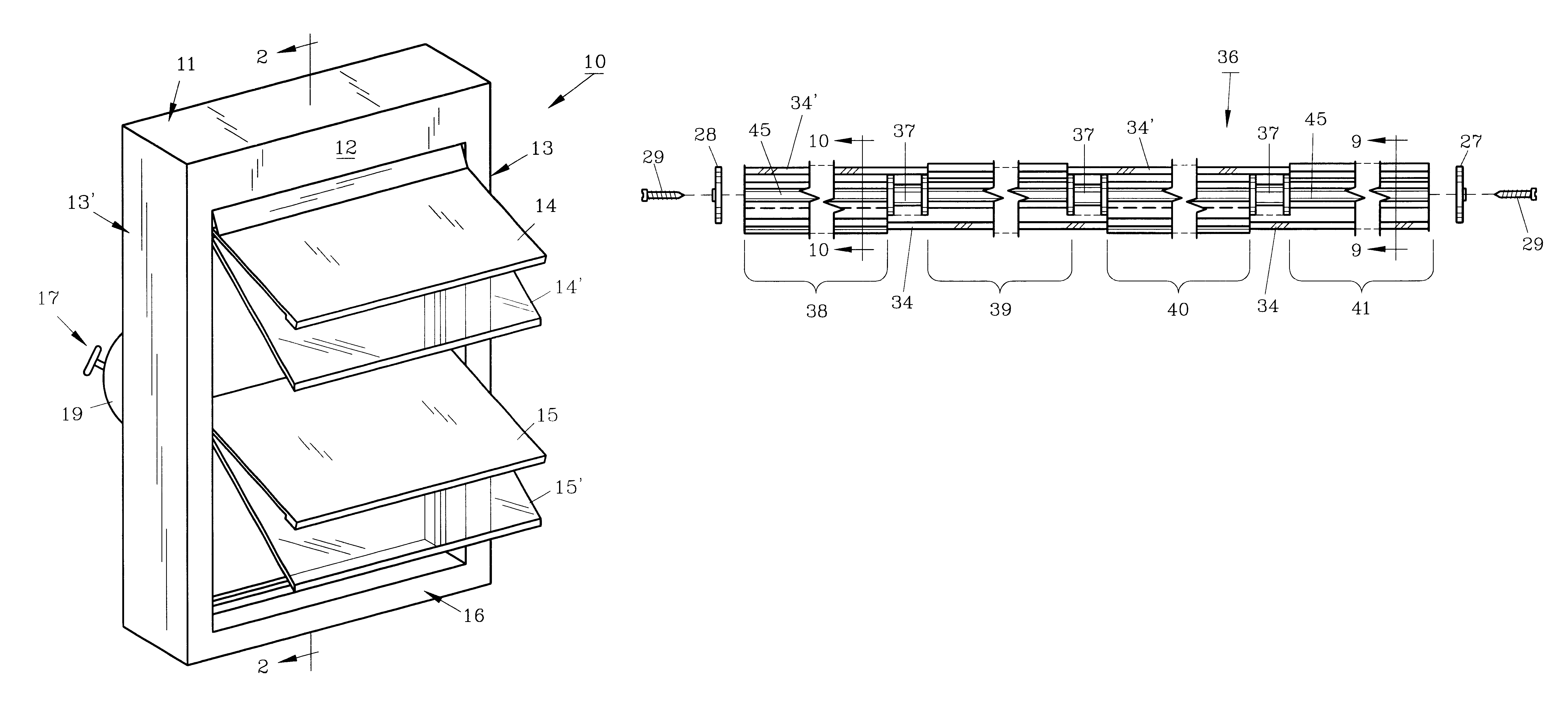
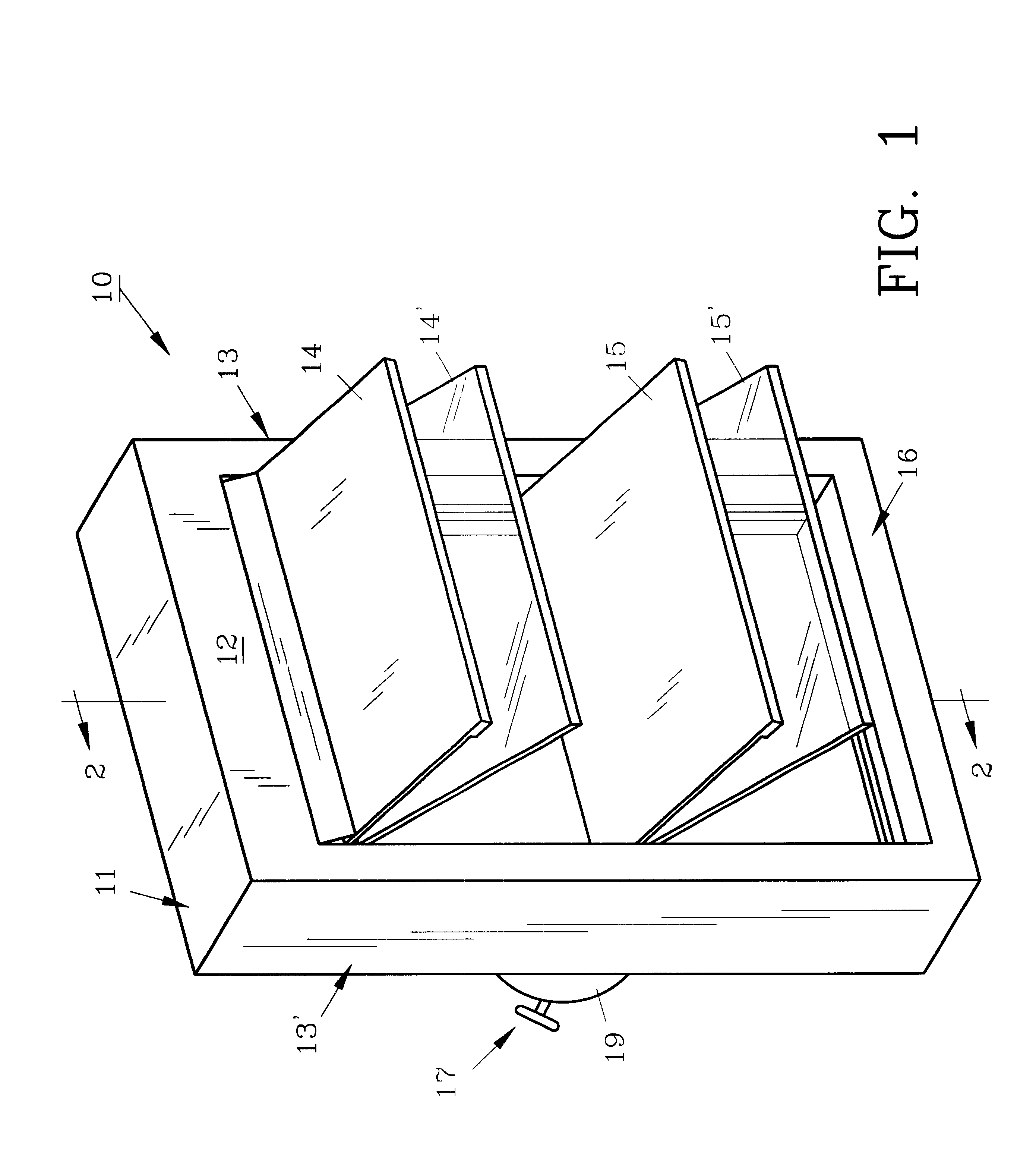
For a better understanding of the invention and its operation, turning now to the drawings, FIG. 1 demonstrates the preferred jalousie assembly 10 used in a conventional jalousie or awning window which includes frame 11 with header 12, jambs 13, 13' and sill 16. Tandem panel pairs 14, 14' and 15, 15' are pivotally joined to window frame 11. As shown front panels 14 and 15 are opaque, being formed of aluminum or other suitable materials. Rear panels 14' and 15' are glass as are usual in jalousie type windows and doors. As will be hereinafter explained in more detail, front panels 14 and 15 are independently operated from rear panels 14' and 15' and can be opened and closed as required. Front aluminum panels 14 and 15 are simultaneously operated by handle 17 of standard operator 19 whereas rear glass panels 14' and 15' are operated by handle 18 (FIGS. 11 and 12) positioned on jamb 13. While only two pairs of aluminum and glass panels are shown in FIG. 1, similar jalousie assemblies co...


PUM


Abstract

A jalousie assembly comprising a plurality of independently adjustable front and rear panels forming tandem pairs. A front panel operator operates the front panels and a rear panel operator operates the rear panels independently from the front panels. Thus, the front panels can be opened independently from the rear panels or together with the rear panels. The front panel may be constructed of aluminum or glass while the rear panel may be constructed of transparent glass.

Description

The invention herein pertains to jalousie assemblies as are used for building windows and doors and particularly pertains to a jalousie assembly having pairs of pivotable panels which are tandemly arranged and independently operated.DESCRIPTION OF THE PRIOR ART AND OBJECTIVES OF THE INVENTIONJalousie type windows and doors have long been used and remain quite popular in tropical climates. The advantages of such jalousie assemblies is that the horizontal panels can be selectively opened and closed to allow breezes for example, from the ocean to ventilate and cool the building without the necessity of air conditioning. This is of particular importance in areas where electricity is extremely expensive or unavailable. Jalousie assemblies generally have one vertical column of panels with each panel formed of a relatively narrow, single glass pane. A typical window may have three or four such panes arranged in this vertical column. The panels are operated by a handle and gears which are m...

Claims


Application Information

Patent Timeline
Patent Type & Authority Patents(United States)
IPC IPC(8): E06B7/02E06B7/094
CPCE06B7/094
Inventor JORDAL, ROBERT L.
Owner JORDAL ROBERT L
Why Eureka
Try Eureka