Dry sectional gate relief valve

a gate relief valve and dry section technology, applied in the field of intake valves, can solve the problems of valve parts corrosion and valve parts corrosion

Inactive Publication Date: 2002-05-07
TASK FORCE TIPS
View PDF16 Cites 34 Cited by
  • Summary
  • Abstract
  • Description
  • Claims
  • Application Information

AI Technical Summary

Benefits of technology

These and other objects are accomplished by providing a relief valve comprising means on an inlet section for connecting the valve to a fluid source, means on an outlet section of the valve for connecting the valve to a suction source, means mounted inside the valve adjacent to the suction source connecting means, for controlling the flow of the fluid through the relief valve, the valve being dry when the valve is closed and connected to the suction source and not connected to the fluid source, and means positioned on the outside of the relief valve and connected to the flow controlling means for adjusting the position of the flow controlling means within the opening of the outlet section. The means on the inlet section of the valve comprises a quick attachment coupling. The means on the outlet section of the valve comprises a s...

Problems solved by technology

However, when the water supply hose is disconnected from the valve, water remains in the valve chamber resulting in corrosion of the valve parts over a period of time.
Water left in the chamber ...

Method used


Image

  • Dry sectional gate relief valve
  • Dry sectional gate relief valve
  • Dry sectional gate relief valve

Examples


Embodiment Construction

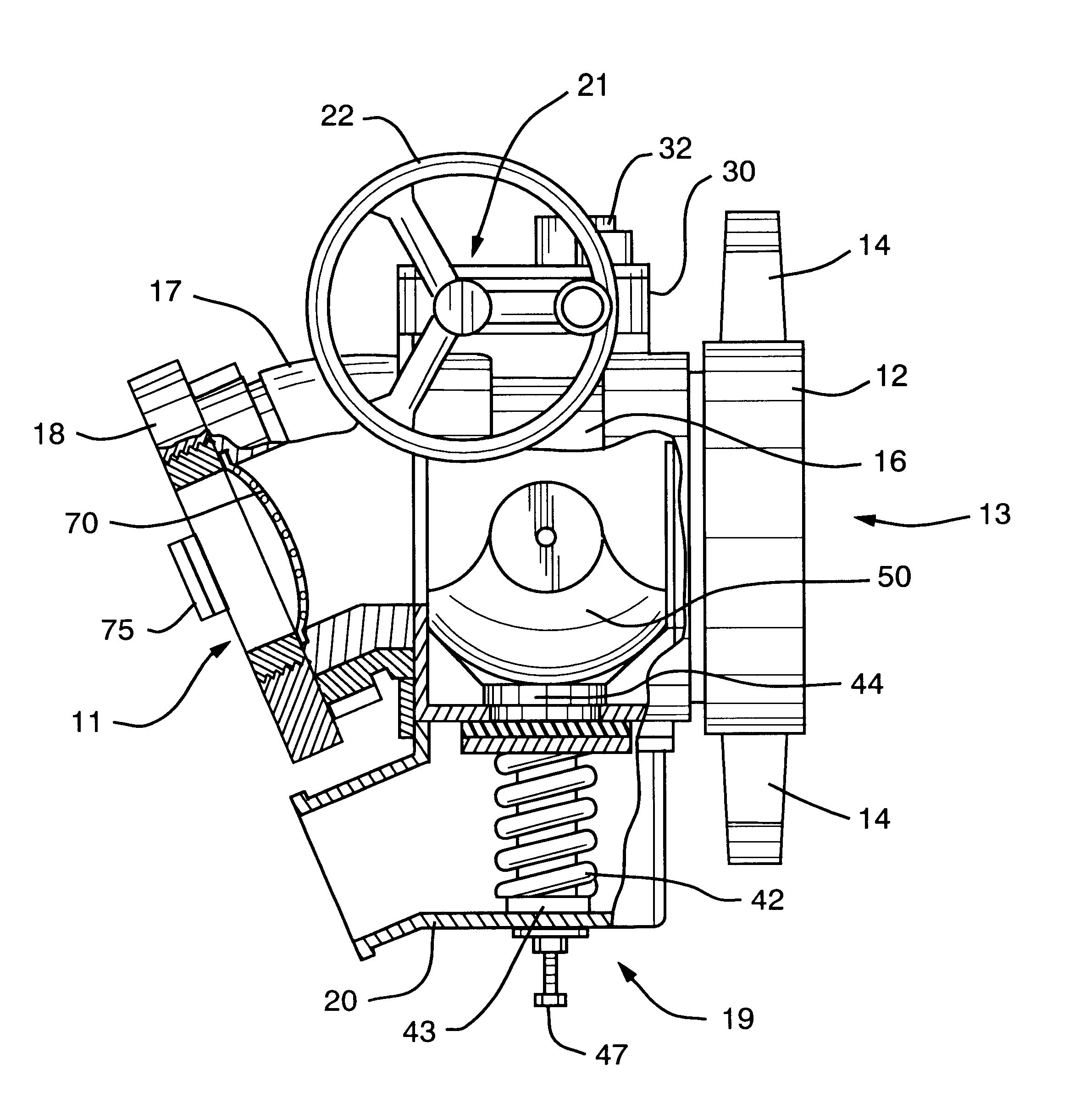
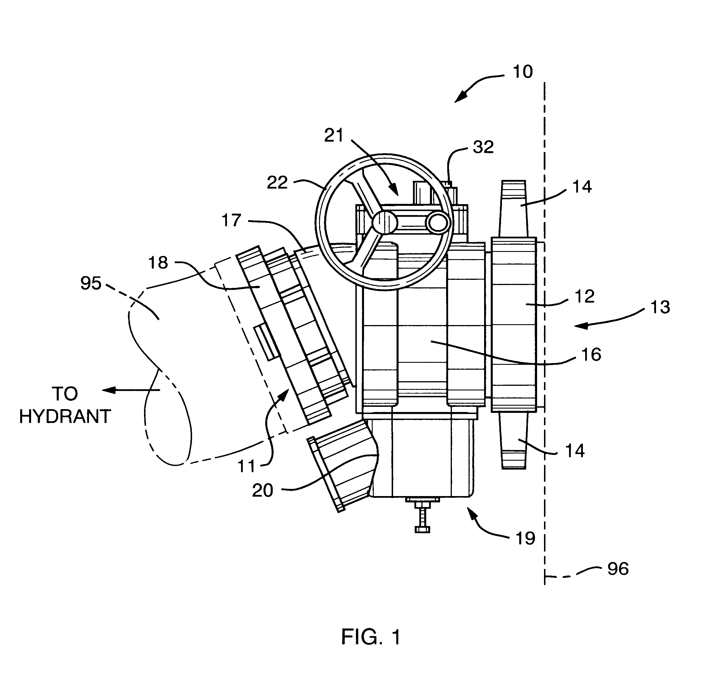
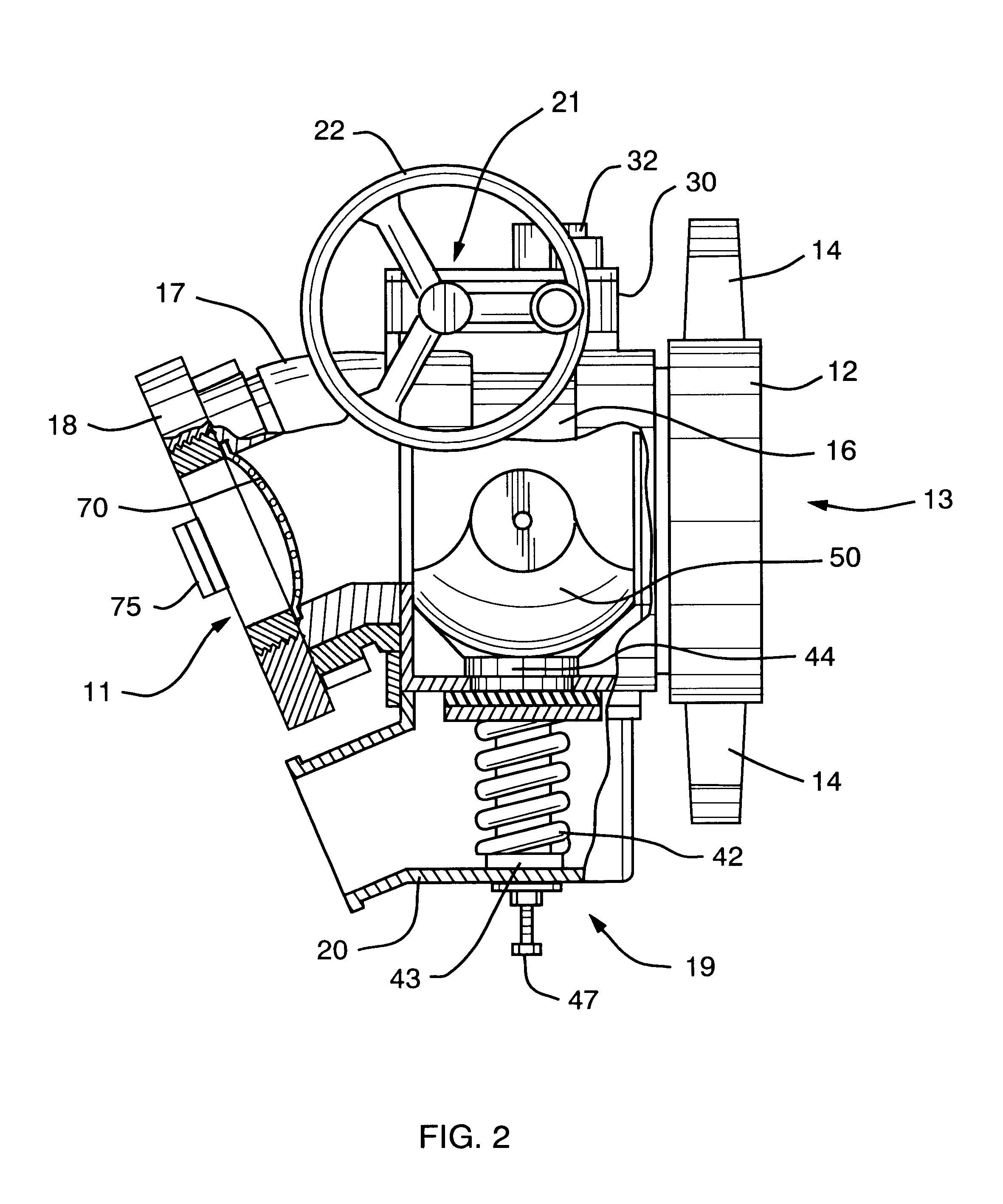
Referring to FIG. 1 and FIG. 2, FIG. 1 shows a side elevational view of a dry relief valve 10, and FIG. 2 shows an enlarged partial cross-sectional view of the invention comprising an inlet section 11, an outlet section 13, a pressure relief section 19 and an actuator section 21. When the valve 10 is in a closed position connected to a pumper fire truck 96 and there is no water source connected to the inlet section 11, the housing 16 is dry thereby eliminating corrosion problems.

Referring to FIGS. 1, 2 and 6, the inlet section 11 connects to a hose 95 extending from a source of water which is provided to the pumper fire truck 96 via valve 10. The inlet section 11 as shown in FIG. 1 comprises a Storz tight coupling 18 attached to an elbow 17 and the elbow 17 attaches to the main housing 16. One skilled in the art will recognize that the inlet section 11 could be embodied by a straight coupling instead of an elbow 17. Another configuration of an inlet section 11 includes a pressure re...


PUM


Abstract

An intake relief valve comprises a bronze sectional gate positioned within the valve chamber adjacent to an outlet section of the valve. A quick attachment coupler of the valve connects the outlet section typically to a pumper fire truck, and a hose from a hydrant or draft source connects to an opposite inlet section of the valve. When the valve is closed and the hose is disconnected from the valve with the valve connected to the pumper fire truck, there is no water remaining in the valve chamber. Any residual water is released by a pit drainage outlet on the bottom wall of the valve. Not having water stored in the valve eliminates corrosion problems within the valve, when the valve is connected to the pumper fire truck.

Description

1. Field of the InventionThe present invention relates to an intake valve generally for use on a pumper fire truck, and in particular to a relief valve having a sectional gate to open and close water flow at the pumper side or outlet section of the valve whereby no water remains in the valve when there is no connection to a water source at the inlet section of the valve.2. Description of Related ArtIt is well known to attach a gated relief valve to a pumper fire truck in order to quickly attach a water supply hose to the valve. However, when the water supply hose is disconnected from the valve, water remains in the valve chamber resulting in corrosion of the valve parts over a period of time.In U.S. Pat. No. 5,178,185, issued Jan. 12, 1993 to Henry J. Stehling and Grady North and assigned to Hydra-Shield Manufacturing, Inc., a suction inlet valve for fire trucks pumpers is shown comprising a valve body having a chamber connected to inlet and outlet openings. A floating valve element...

Claims


Application Information

Patent Timeline
IPC IPC(8): F16K11/10F16K11/20
CPCF16K11/205Y10T137/8292
Inventor GUNDRY, DAVID K.
Owner TASK FORCE TIPS
Why Eureka
Try Eureka