
Method and apparatus for detecting the presence of an object

a detection method and object technology, applied in the field of intrusion detection systems, can solve the problems of ir sensor from a moving platform, prone to a relatively high incidence of false alarms, and each individual sensor signal of such systems is subject to the same drawbacks,

Inactive Publication Date: 2002-05-07
HANGER SOLUTIONS LLC
View PDF18 Cites 112 Cited by
  • Summary
  • Abstract
  • Description
  • Claims
  • Application Information

AI Technical Summary

Problems solved by technology

Each individual sensor signal of such systems is subject to the same drawbacks as single-sensor systems.
Single-sensor systems are prone to a relatively high incidence of false alarms because intruders may share similar characteristics with a non-intruder.
Further, the use of a passive IR sensor from a moving platform presents at least one additional problem.
It is difficult, if not impossible, to determine if a change in average temperature recorded by the IR sensor is due to an intruder or due to a change in the background temperature, because the IR sensor's field of view changes with its motion.
Traditional intrusion detection systems are not able to provide a simple and low-cost method of performing human detection from a moving platform.
Rather, existing intrusion detection techniques often require computationally demanding image processing algorithms.
Further, existing systems have not been able to utilize commercial passive infrared or active Doppler sensors to achieve such human detection.
A number of different techniques have been attempted for the detection of a person from a moving platform, but each has been unsuccessful.
However, the signal from such a system may be so small that other disturbances present in the background may overwhelm the signal in question, making its measurement practically impossible.
Acoustic sensors have also been considered, but background noise can easily overwhelm the desired signal or cause false alarms.
Also, real-time video and infrared cameras with associated image processing have been considered for robotics applications, but the complexity, power consumption, and required computing power are incompatible with a small, battery-powered robot platform.

Method used


Image

  • Method and apparatus for detecting the presence of an object
  • Method and apparatus for detecting the presence of an object
  • Method and apparatus for detecting the presence of an object

Examples


Embodiment Construction

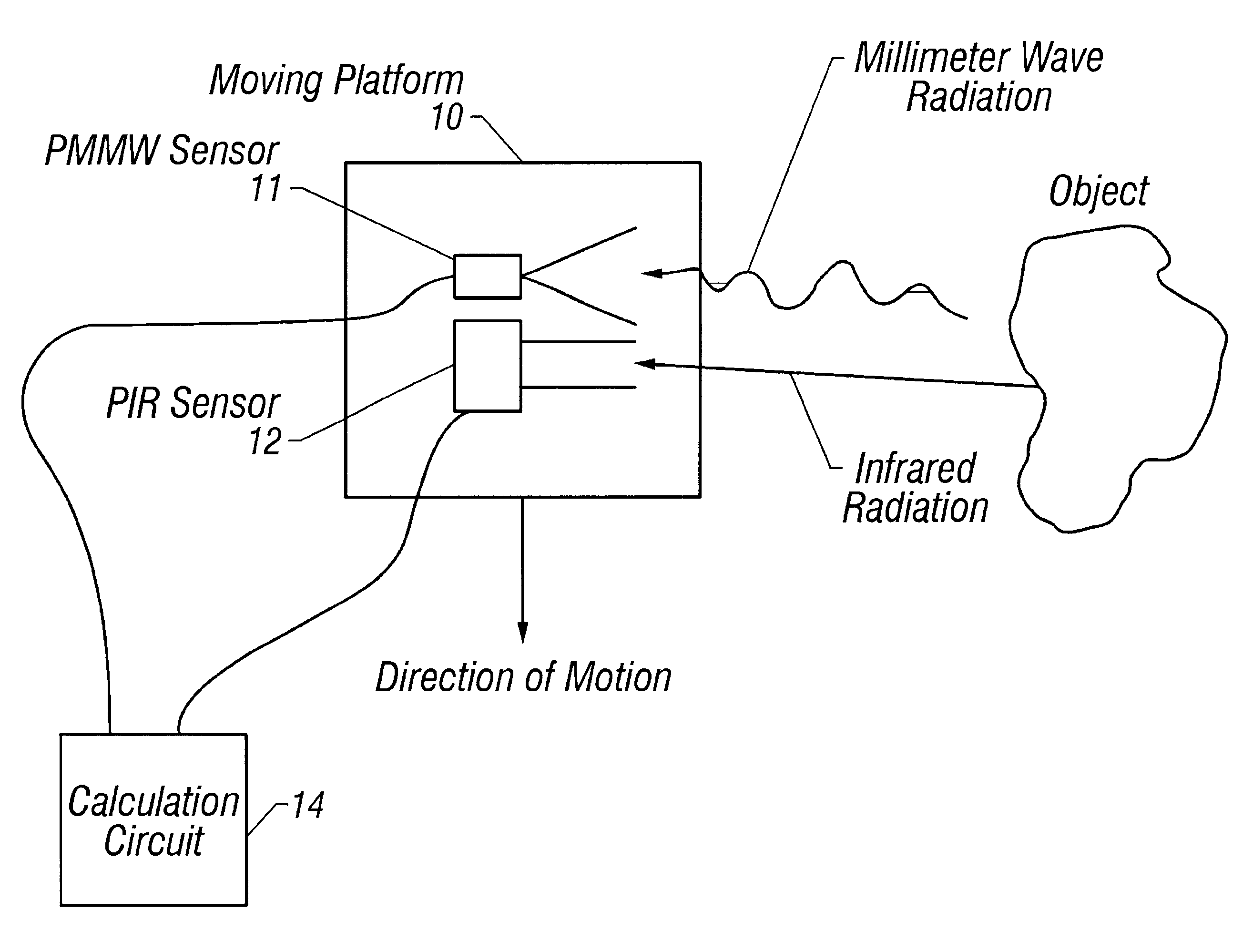
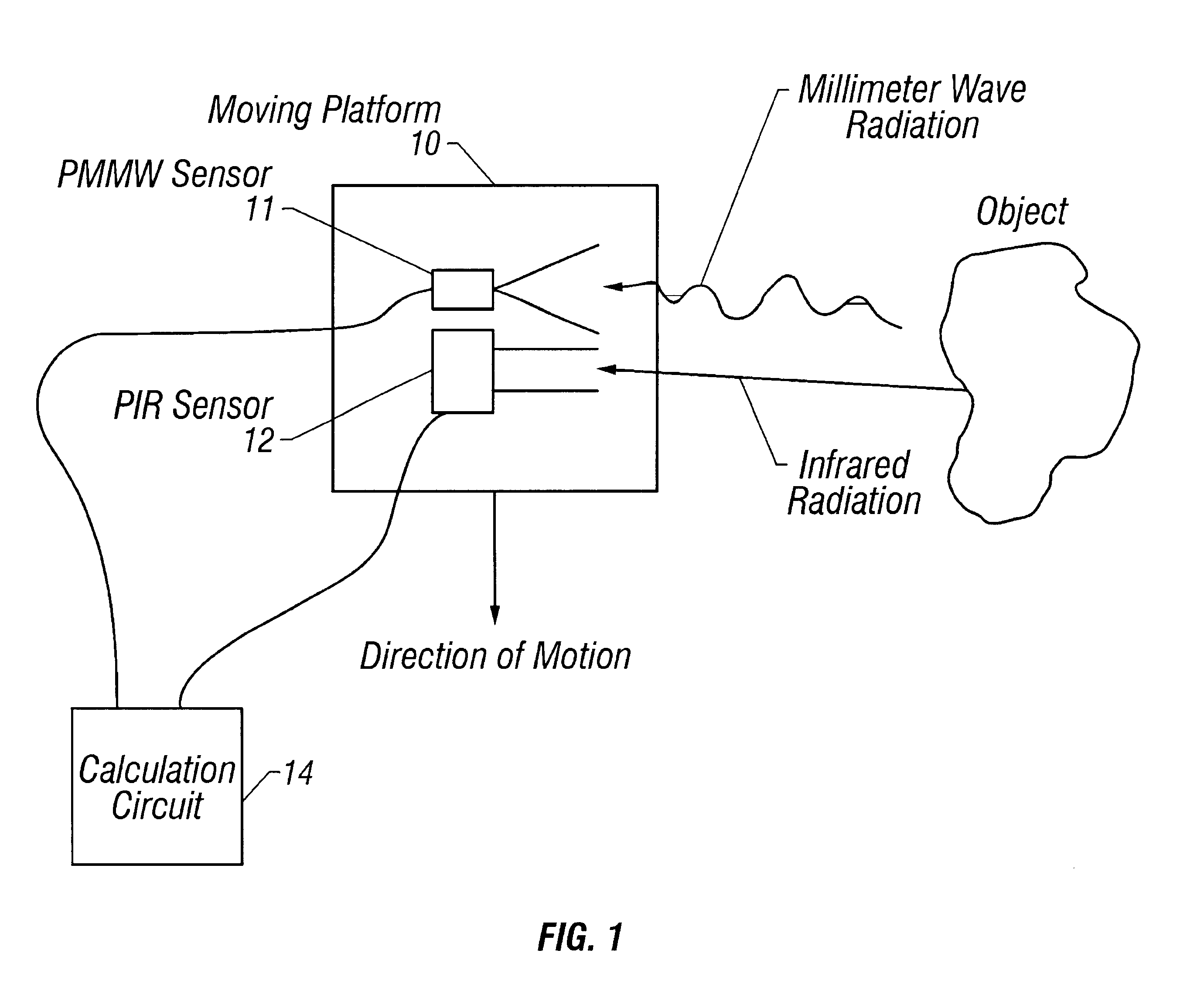
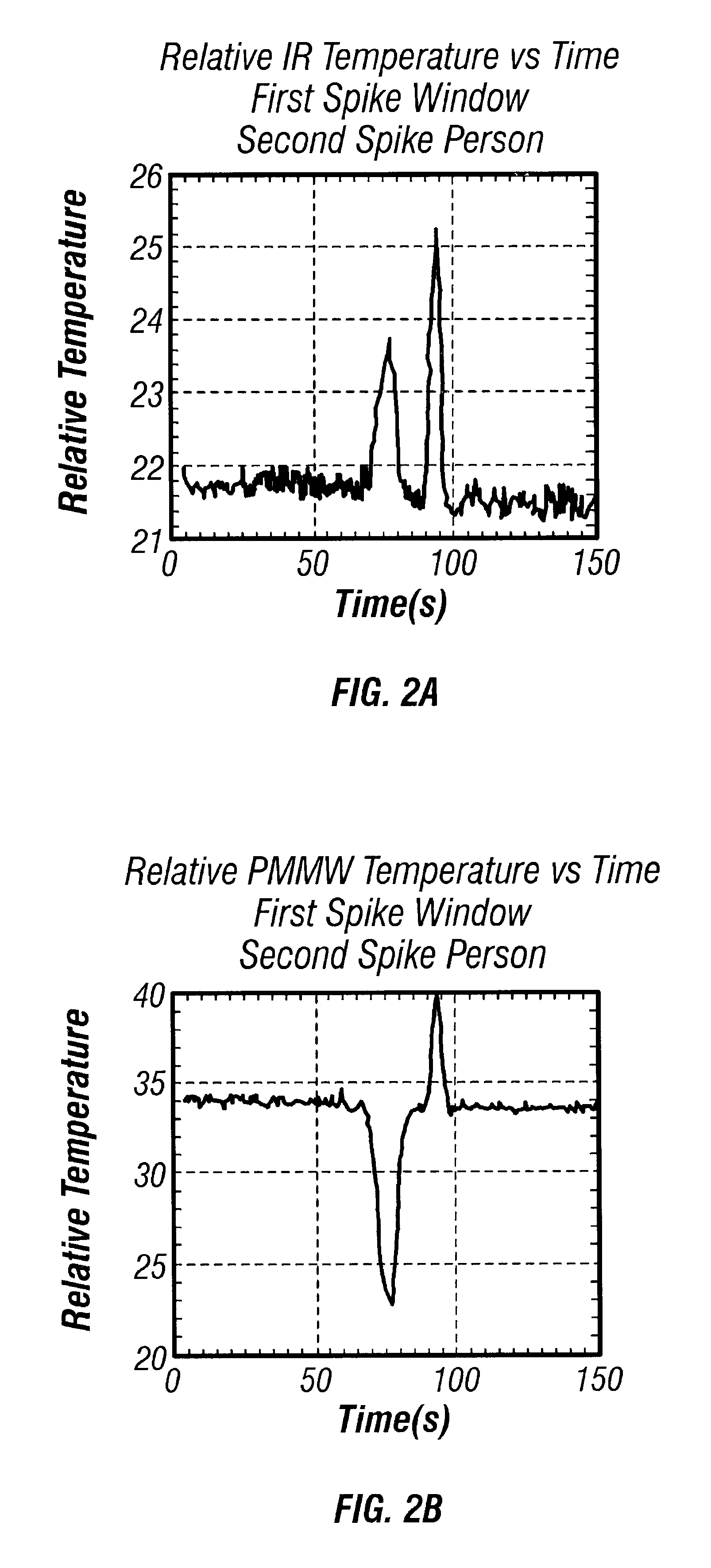
FIG. 1 shows an exemplary embodiment of the present invention, in which a first sensor 11 and a second sensor 12 are configured on a moving platform 10 to detect the presence of a human in a side-looking configuration. Platform 10 may move and / or rotate in any direction. In particular, platform 10 and / or sensors 11 and 12 may move so as to achieve a 360 degree view. As illustrated, the sensors 11 and 12 are coupled to a calculation circuit 14. As used herein, a "circuit" may refer to any device that may process signals and / or data. In particular, a circuit may refer to a device that receives, processes, and / or compares signals or data. Thus, a circuit may refer to a one dimensional processor, a computer, a microprocessor, software adapted to run on a computer or any other suitable device. In one embodiment, calculation circuit 14 includes a microprocessor and the commercially available software LabView produced by National Instruments (Austin, Tex.). As used herein, a "calculation c...


PUM


Abstract

A method and apparatus for detecting and classifying an object, including a human intruder. The apparatus includes one or more passive thermal radiation sensors that generate a plurality of signals responsive to thermal radiation. A calculation circuit compares the plurality of signals to a threshold condition and outputs an alarm signal when the threshold condition is met, indicating the presence of the object. The method includes detecting thermal radiation from an object at a first and second wavelength and generating a first and second responsive signal. The signals are compared to a threshold condition that indicates whether the object is an intruder.

Description

The present invention relates generally to a method and apparatus for detecting the presence of an object. More specifically, the present invention relates to a method and apparatus to distinguish between human and non-human objects, from a movable platform.DESCRIPTION OF RELATED ARTTypical intrusion detection systems often consist of one or more types of fixed volumetric detectors. For example, some systems utilize stationary microwave devices that emit microwave radiation at a known frequency and analyze returned radiation to determine changes in frequency induced by moving objects, which produce a Doppler-effect shift in the received radiation. Other systems use passive infrared (IR) detectors sensitive to IR radiation to determine when a heat source, such as a human body, moves into its field of view.Some systems attempt to reduce the occurrence of false alarms by combining two or more sensors. For instance, a microwave sensor and an IR sensor have been deployed in a vehicle or ...

Claims


Application Information

Patent Timeline
Patent Type & Authority Patents(United States)
IPC IPC(8): G01J5/10G08B17/12G08B13/189G08B13/19G01J5/08G01V8/00G08B13/24G08B29/18
CPCG01J5/08G01J5/0846G01J5/089G01V8/005G08B13/19G08B13/2494G08B17/005G08B17/12G08B29/183G01J5/10G01J5/0025G01J5/025G01J5/047Y10S250/01G01J5/07
Inventor FISHER, DAVID L.ROGERS, ROBERT L.
Owner HANGER SOLUTIONS LLC
Learn More