Control apparatus and control method for motor vehicle

a technology of control apparatus and motor vehicle, which is applied in the direction of electrical control, hybrid vehicles, non-mechanical valves, etc., can solve the problems of engine rotation, fuel consumption deterioration, and motor regenerative efficiency reduction

Inactive Publication Date: 2002-05-21
TOYOTA JIDOSHA KK
View PDF9 Cites 70 Cited by
  • Summary
  • Abstract
  • Description
  • Claims
  • Application Information

AI Technical Summary

Problems solved by technology

As a result, regenerative efficiency of the motor decreases and fuel consumption deteriorates.
This problem arises especially in a vehicle constructed such that rotation of an engine continues during the traveling of the vehicle even if fuel supply has been stopped.
Even in a vehicle constructed such that an engine can be stopped independently of the traveling of the vehicle, a similar problem arises from a timing when fuel supply is stopped to a timing when the engine is actually controlled to be stopped.
However, since the throttle valve is completely opened, a large amount of cold outside air flows into the exhaust system through the engine.
Therefore, the temperature of a catalyst provided

Method used


Image

  • Control apparatus and control method for motor vehicle
  • Control apparatus and control method for motor vehicle
  • Control apparatus and control method for motor vehicle

Examples


first embodiment

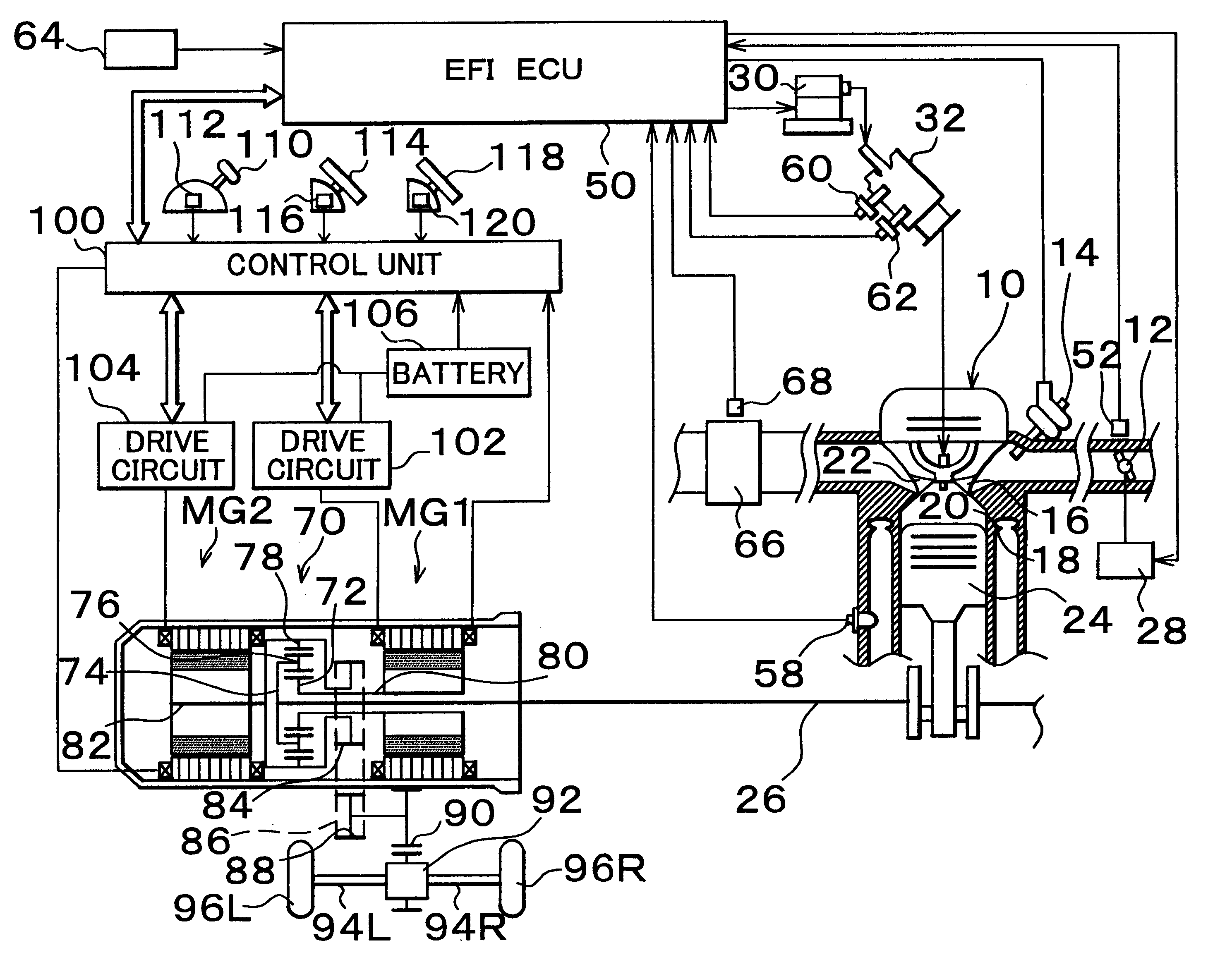
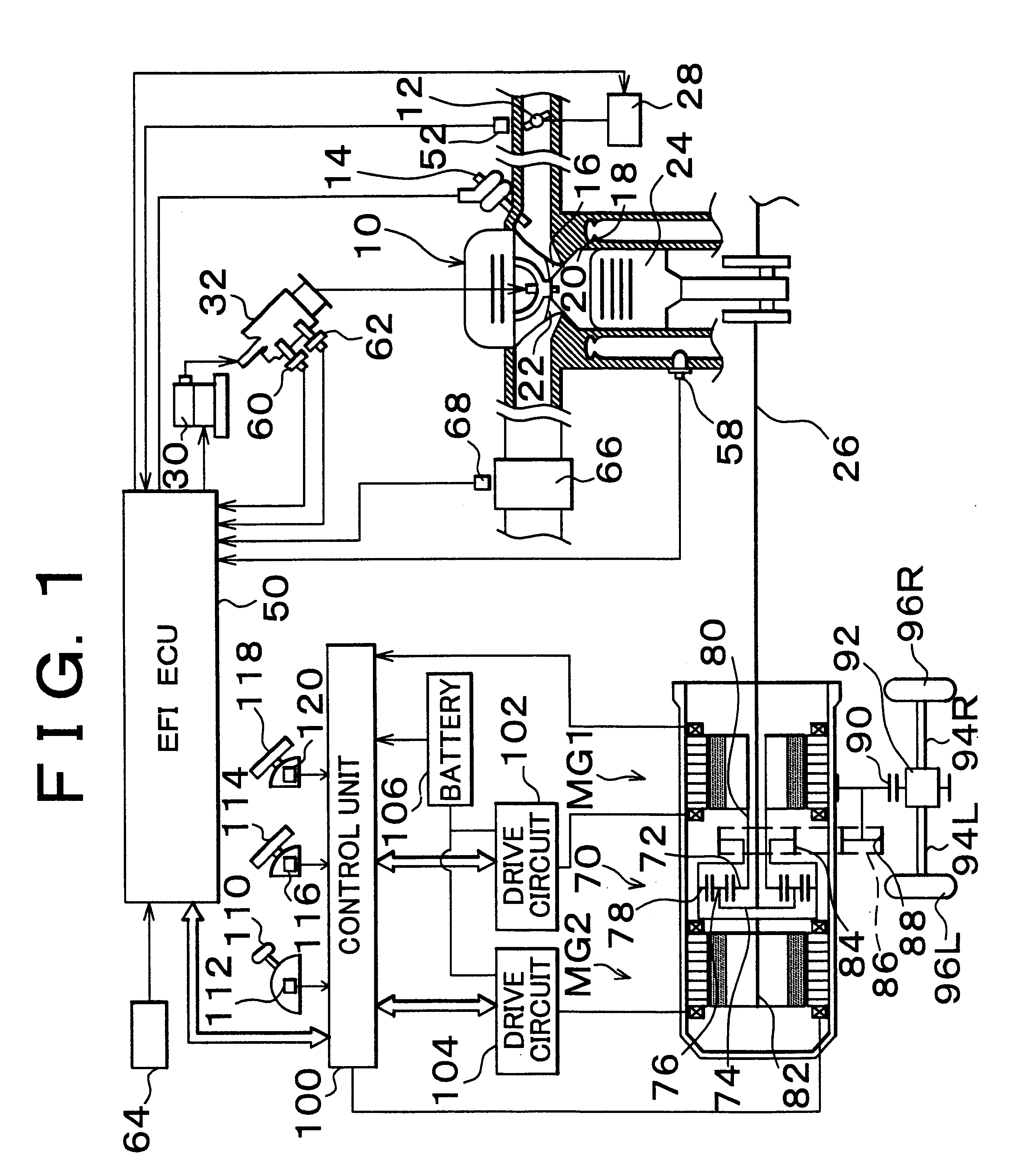
In a first embodiment, if the catalyst temperature sensor 68 (FIG. 1) detects during fuel cut that the temperature Tca of the catalyst 66 is higher than a predetermined temperature Tca1, the actuator 28 opens the throttle valve 12 to increase an amount of intake air. On the other hand, if the temperature Tca of the catalyst 66 has become equal to or lower than the predetermined temperature Tca1, the throttle valve 12 is then closed.

FIG. 3 shows a control flow executed by the EFIECU 50 to realize this control.

It is determined in STEP 202 whether or not fuel supply has been stopped. If fuel supply has not been stopped, the problem of pumping loss does not arise. Thus, operation immediately exits the control flow.

If it is determined that fuel supply has been stopped, operation proceeds to STEP 204 where it is determined whether or not the catalyst temperature Tca is higher than the predetermined temperature Tca1. If the catalyst temperature Tca is higher than the predetermined temperat...

second embodiment

In a second embodiment, during fuel cut, the opening degree TA of the throttle valve 12 is increased and set in accordance with a temperature Tca of the catalyst in the exhaust system.

FIG. 4 shows an exemplary map of temperatures Tca of the catalyst stored in the EIECU 50 to realize this control and opening degrees TA of the throttle valve 12 set in accordance with the catalyst temperatures Tca.

As is apparent from FIG. 4, if the catalyst temperature Tca is lower than a predetermined temperature Tca2, the opening degree TA of the throttle valve 12 is maintained at a value corresponding to its completely closed state. If the catalyst temperature Tca drops below the predetermined temperature Tca2, it tends to be difficult for the catalyst to perform its intrinsic function. To be more specific, the predetermined temperature Tca2 is slightly lower than the predetermined temperature Tca1 of the first embodiment. As the catalyst temperature Tca becomes higher than the predetermined tempera...

third embodiment

In a third embodiment, during fuel cut, the opening degree TA of the throttle valve 12 is increased and exhaust valves of the engine are driven in their closing directions in accordance with a temperature Tca of the catalyst in the exhaust system. Meanwhile, intake valves are kept open to further reduce pumping loss.

In order to realize this control, the third embodiment employs a mechanism capable of keeping the intake and exhaust valves closed and controlling them. A construction capable of freely controlling the opening and closing of the intake and exhaust valves independently of positions of pistons (without depending on positions of the pistons) is known in itself. For example, Japanese Patent Application Laid-Open No. 9-303122 discloses such a construction. In implementing the third embodiment of the invention, the structure for keeping the exhaust valves closed is not specifically limited. Here, one example of the construction will be described.

FIG. 5 is a longitudinal sectio...


PUM


Abstract

A control apparatus for a motor vehicle detects a catalyst temperature during fuel cut. If the catalyst temperature is higher than a predetermined temperature, the control apparatus almost completely opens a throttle valve and increases an amount of intake air to thereby reduce pumping loss. If the catalyst temperature is equal to or lower than the predetermined temperature, the throttle valve is almost completely closed. Thereby it becomes possible to reduce pumping loss of the engine while preventing an excessive decrease in catalyst temperature.

Description

1. Field of the InventionThe invention relates to a control apparatus and method wherein supply of fuel to an engine may be stopped even in a traveling state of the vehicle.2. Description of the Related ArtAs a drive source for driving a vehicle, a hybrid vehicle equipped with an engine and a motor having a regenerative function is known from Japanese Patent Application Laid-Open No. 5-229351. In such a vehicle, with a view to improving fuel consumption, supply of fuel to an engine is stopped (fuel cut) during deceleration of the vehicle.During deceleration, a throttle valve (a valve for adjusting an amount of intake air) is generally completely closed. Thus, if supply of fuel to the engine is stopped in this state, pistons in the engine reciprocate within an enclosed space. Reciprocating movement of the pistons offers resistance against the traveling of the vehicle. As a result, regenerative efficiency of the motor decreases and fuel consumption deteriorates. This problem arises es...

Claims


Application Information

Patent Timeline
IPC IPC(8): B60K6/04B60K6/00F02D41/12F02M69/28F01L9/04F02D41/00F02D41/02F02D13/04F02D43/00B60K6/20B60K6/445B60W10/06B60W10/26B60W20/00F01L9/20F02D13/02F02D29/02F02D41/04F02D45/00
CPCB60K6/445B60W10/06B60W10/26F01L9/04F02D41/0235F02D41/123F02M69/28F02D13/04B60L2240/445B60W2510/068Y02T10/6239F02D2200/0802Y10S903/903Y02T10/62F01L9/20
Inventor SUZUKI, NAOTOTAKAOKA, TOSHIFUMISUZUKIOKADA, DAIMON
Owner TOYOTA JIDOSHA KK
Why Eureka
Try Eureka