Screwed steel pile and method of construction management therefor

Inactive Publication Date: 2002-05-28
NIPPON STEEL CORP
View PDF28 Cites 35 Cited by
  • Summary
  • Abstract
  • Description
  • Claims
  • Application Information

AI Technical Summary

Benefits of technology

The tenth present invention provides a screwed steel pile according to claim 9, wherein the inside of the bottom plate ring is protruded from the inside face of the

Problems solved by technology

In the pile driving method or the pile displacing method, which is a conventional construction method for foundation piles used for construction of buildings and others, problems may be caused by noise and vibration generated in the process of construction.
However, the following problems may be encountered in the above screwed steel pile.
Therefore, it is difficult for soil and sand, which is located at a position lower than the bottom plate, to be moved upward in the process of construction.
Accordingly, it becomes difficult to generate a sufficiently high intensity of thrust.
Especially when the soil at the bottom plate portion is hard and the soil close to the wing is soft, it very difficult for soil and sand to be moved to an upper portion of the wing.
However, the following problems may be encountered according to this structure.
Therefore, it is impossible to obtain an effectively high intensity of bearing capacity.
However, even if the above steel pipe pile is used, it is impossible to enhance the construction accuracy of the steel pipe pile.
The reason why it is impossible to enhance the construction accuracy the steel pipe pile is that configurations of the spiral wing and the forward end portion of the steel pipe are not appropriate.
In this steel pipe pile, since this incomplete wing is attached to the side of the steel pipe, a projected area of the wing exceeds 360.degree., and the construction efficiency is deteriorated.
When a capacity of a pile driver used for burying the pile is insufficient, it becomes necessary to replac

Method used


Image

  • Screwed steel pile and method of construction management therefor
  • Screwed steel pile and method of construction management therefor
  • Screwed steel pile and method of construction management therefor

Examples


embodiment 1

There is shown an embodiment in which a steel pipe pile, the diameter of which was 406.4 mm .phi., was controlled for construction so that penetration could be continued and completed while penetrative resistance was being found.

Other conditions of construction of this steel pipe pile are described below. Diameter Dp' of the action circle of the bottom plate was 270.9 mm, diameter Dw' of the action circle of the wing was 514.8 mm, angle .theta. of the wing with respect to a face perpendicular to the pile axis was 5.degree., and designed penetrative resistance was previously calculated to be 97.0 t.

In construction, coefficient .alpha. of friction between the ground and a steel plate was 0.3, coefficient .gamma. of resistance of the perpendicular cutter was 0.03, ratio "a" of transfer of upper load Lt and torque Tt to the forward end of the pile was 0.9, and horizontal blade resistance Qwh was neglected because it was very low. Under the above conditions, changes in penetrative resist...

embodiment 2

There is shown an embodiment in which a steel pipe pile, the diameter of which was 508.0 mm.phi., was controlled for construction so that penetration could be continued and completed while penetrative resistance was being found.

Other conditions of construction of this steel pipe pile are described below. Diameter Dp' of the action circle of the bottom plate was 338.7 mm, diameter Dw' of the action circle of the wing was 790.2 mm, angle .theta. of the wing with respect to a face perpendicular to the pile axis was 5.degree., and designed penetrative resistance was previously calculated to be 136.8 t.

In construction, the coefficient .alpha. of friction between the ground and a steel plate was 0.3, the coefficient .gamma. of resistance of the perpendicular cutter was 0.03, ratio "a" of transfer of upper load Lt and torque Tt to the forward end of the pile was 0.9, and the horizontal cutter resistance Qwh was neglected because it was very low. Under the above conditions, changes in penet...

embodiment 3

There is shown an embodiment in which a steel pipe pile, the diameter of which was 609.6 mm.phi., was controlled for construction so that penetration could be continued and completed while penetrative resistance was being found.

Other conditions of construction of this steel pipe pile are described below. Diameter Dp' of the action circle of the bottom plate was 406.4 mm, diameter Dw' of the action circle of the wing was 772.2 mm, angle .theta. of the wing with respect to a face perpendicular to the pile axis was 5.degree., and designed penetrative resistance was previously calculated to be 218.2 t.

In construction, the coefficient .alpha. of friction between the ground and a steel plate was 0.3, coefficient .gamma. of resistance of the perpendicular cutter was 0.03, ratio "a" of transfer of upper load Lt and torque Tt to the forward end of the pile was 0.9, and horizontal blade resistance Qwh was neglected because it was very low. Under the above conditions, changes in penetrative re...


PUM


Abstract

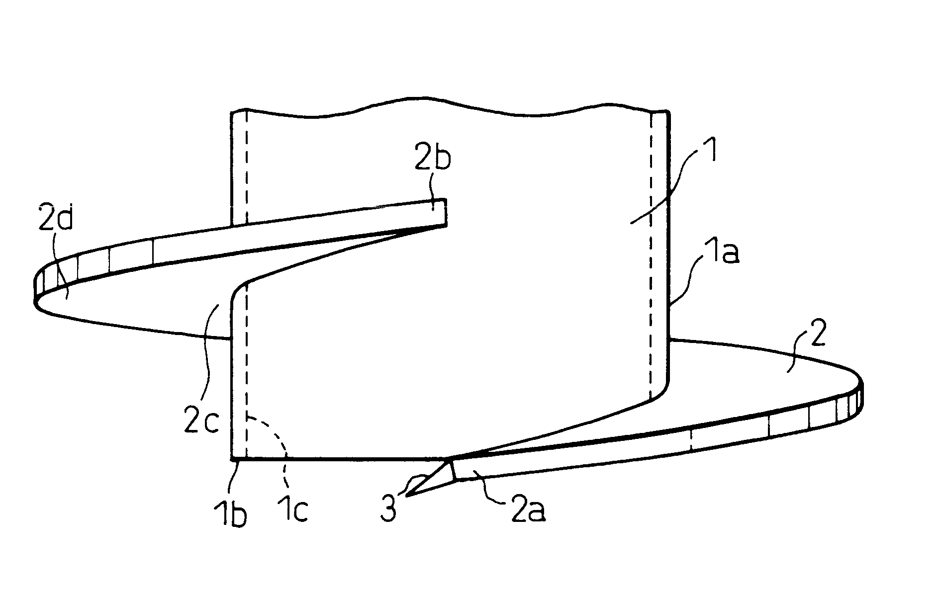
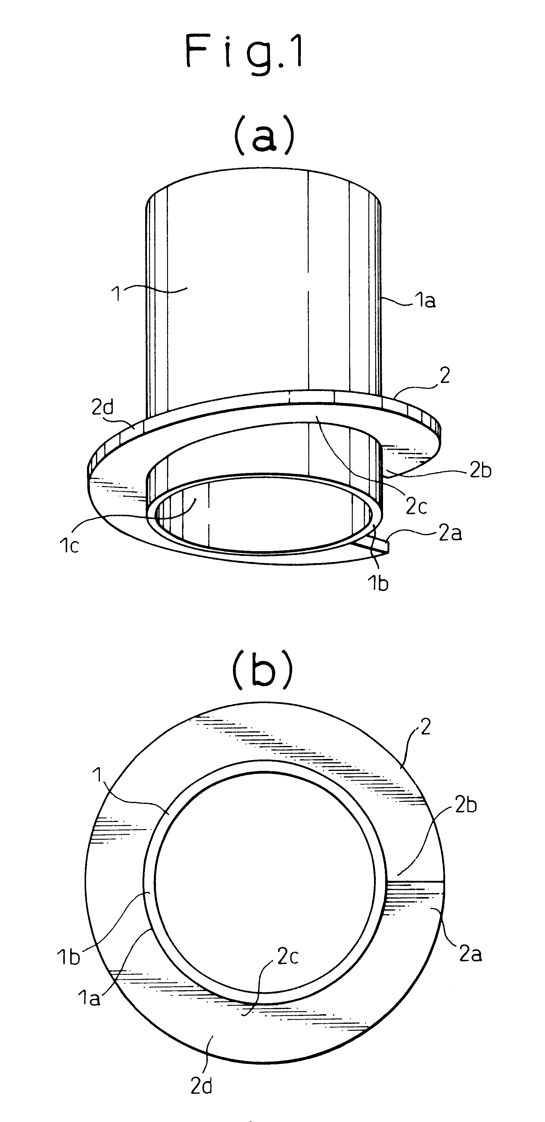
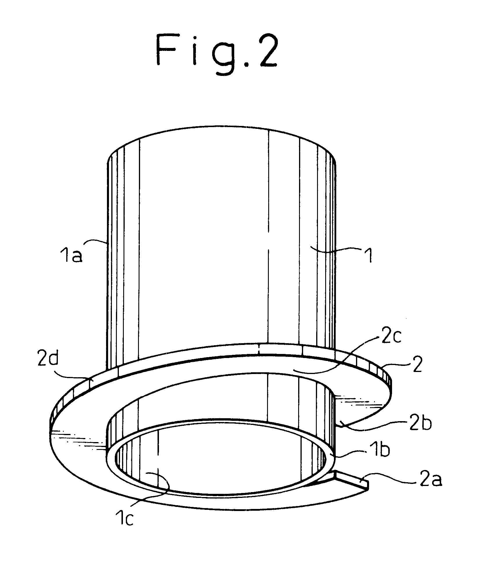
A screwed steel pile has a main pile body which is a hollow pipe. The pile end of the main pile body is open. One or a plurality of wings are arranged on the outside of the pile end portion of the main pile body. An excavating blade is attached to the pile end portion of the wing. The excavating blade has a cross-sectional area less than that of the wing and is attached to the wing where the upper and lower surfaces of the wing and the blade are continuously connected to each other at the outside of the pile end portion.

Description

The present invention relates to steel piles used for foundation of buildings and others. More particularly, the present invention relates to screwed steel piles-having blades for digging and also relates to a method of construction management therefor.DESCRIPTION OF THE PRIOR ARTIn the pile driving method or the pile displacing method, which is a conventional construction method for foundation piles used for construction of buildings and others, problems may be caused by noise and vibration generated in the process of construction. In order to solve the above problems, screwed steel piles have already been proposed. For example, Japanese Examined Patent Publication No. 2-62648 discloses a screwed steel pile characterized in that: an opening of a forward end portion of a steel pile body is closed by a bottom plate; a excavation blade is provided on the bottom plate so as to reduce a penetrative resistance of the pile; and a spiral wing is provided on an outer face of a lower end por...

Claims


Application Information

Patent Timeline
IPC IPC(8): E02D7/22E02D5/22E02D5/56E02D7/00E02D11/00
CPCE02D5/56E02D7/22E02D2300/0029E02D2200/1607E02D2300/00E02D2200/143
Inventor SAEKI, EIICHIROOOKI, HITOSHITAKEDA, TOMOKI
Owner NIPPON STEEL CORP
Why Eureka
Try Eureka