Injection molding unit for an injection molding machine

Inactive Publication Date: 2002-05-28
HEHL KARL
View PDF10 Cites 21 Cited by
  • Summary
  • Abstract
  • Description
  • Claims
  • Application Information

AI Technical Summary

Problems solved by technology

Because the two hollow shaft motors nest in one another, they can only be replaced as one unit, which increa

Method used


Image

  • Injection molding unit for an injection molding machine
  • Injection molding unit for an injection molding machine
  • Injection molding unit for an injection molding machine

Examples


Embodiment Construction

The invention is now described in more detail in an exemplary manner with reference to the enclosed drawings. The exemplified embodiments, however, are not examples which are meant to restrict the concept according to the invention to a specific physical arrangement.

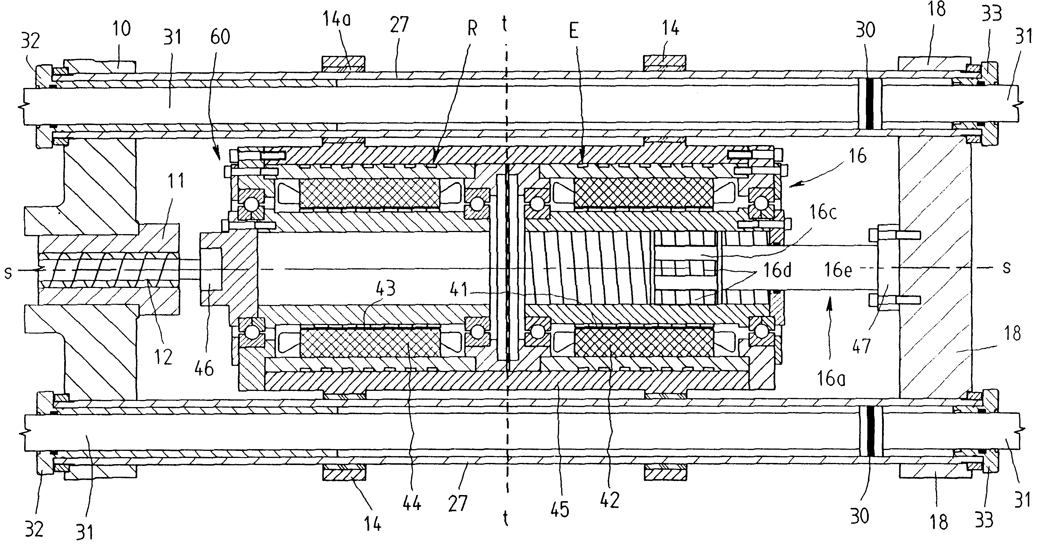
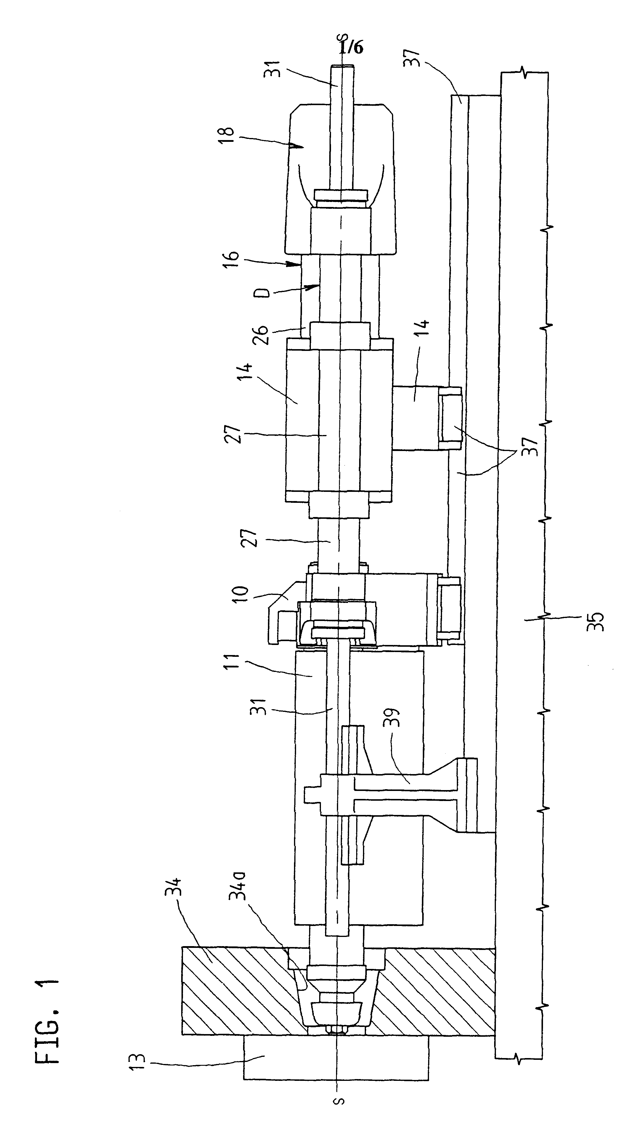
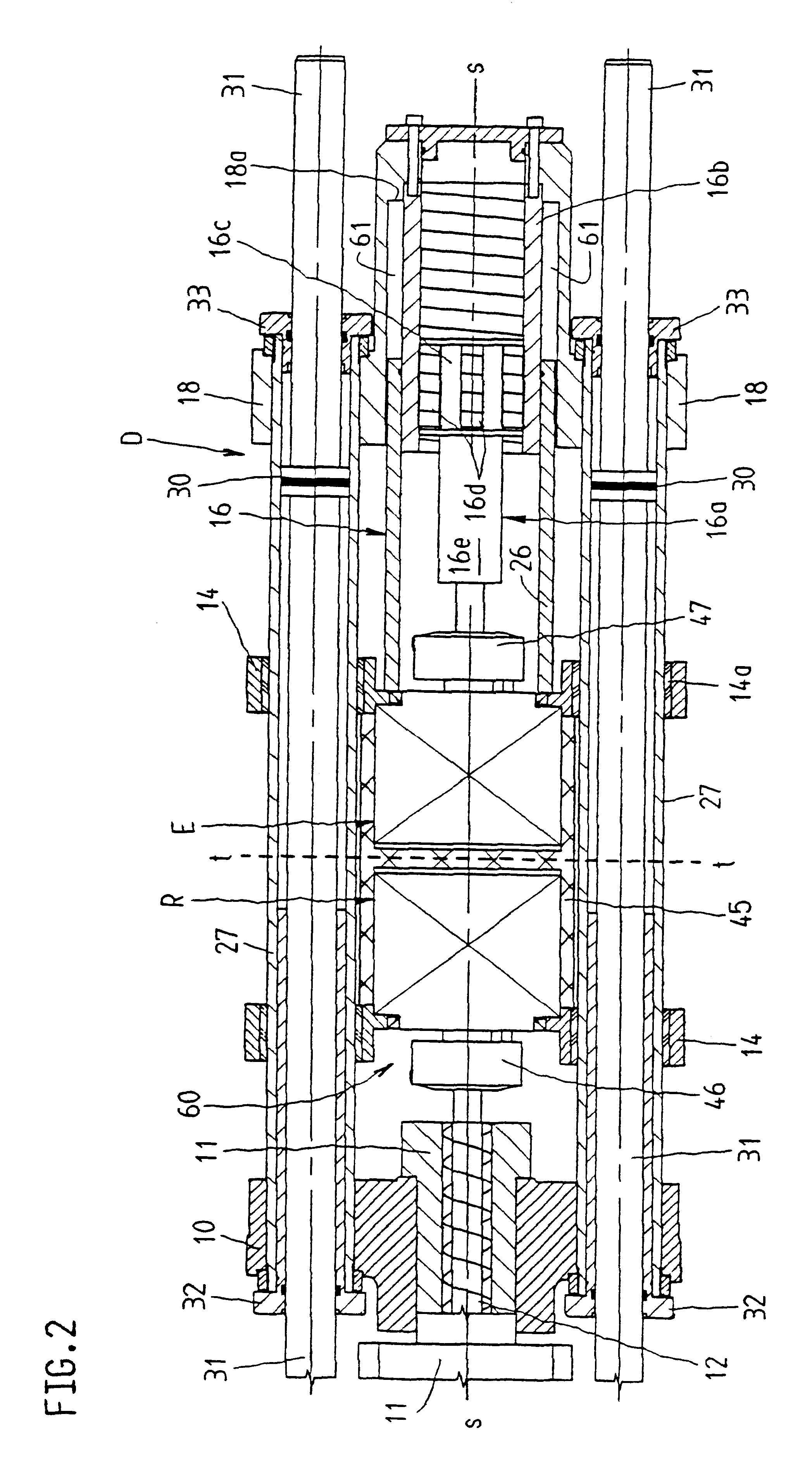
The injection molding unit represented schematically in FIG. 1 is a component part of an injection molding machine and is disposed on the machine base 35 of this injection molding machine. When injecting into a mold 13, a part of which can be seen on the left hand side in FIG. 1, the injection molding unit engages an opening 34a in a stationary mold carrier 34. The injection molding unit on an injection molding machine is for processing plasticisable substances, essentially for injecting these substances, e.g. plastic materials, ceramic substances and other powdery substances into the cavity of the mold 13.

In accordance with FIG. 1, the injection molding machine has a carrier block 10 for accommodating a plasticizing cyl...


PUM

PropertyMeasurementUnit
Lengthaaaaaaaaaa
Areaaaaaaaaaaa
Displacementaaaaaaaaaa

Abstract

In an injection molding unit for an injection molding machine, two electric drives are provided as electromechanical injection unit and electromechanical dosing unit, the axis of which are aligned with the axis of injection. A compact injection molding unit that is easy to assemble and maintain is achieved due to the fact that the first and second electric drives are disposed on the injection bridge on both sides of a separating plane that extends substantially crosswise to the axis of injection and separates the area of influence of the first electric drive from the area of influence of the second electric drive.

Description

FIELD OF THE ARTThe invention relates to an injection molding unit for an injection molding machine for the processing of plastic materials and other plasticisable substances . An injection molding unit of this type is for injecting these substances into a mold which can be fixed on the injection molding machine, ceramic substances or other powdery substances being also considered, for example, as the plasticisable substances to be injected.DESCRIPTION OF THE RELATED ARTAn injection molding unit of this type, known in EP 0 662 382 B1, has two electric drives for the screw drive. One motor is for carrying out the rotary motion of the screw, that is for dosing the substance, the other motor is for carrying out the axial displacement of the screw. The two electric drives are configured as hollow-shaft motors and are disposed with their axes in alignment with the axis of the screw and consequently with the axis of injection. To guarantee the interaction of the two motors, they are dispo...

Claims


Application Information

Patent Timeline
IPC IPC(8): B29C45/03B29C45/07B29C45/50B29C45/46
CPCB29C45/07B29C45/5008B29C2045/504
Inventor HEHL, KARL
Owner HEHL KARL
Why Eureka
Try Eureka