Method and apparatus for efficient measurement of reciprocal multiport devices in vector network analysis

a multi-port device and vector network technology, applied in the direction of measurement devices, resistance/reactance/impedence, instruments, etc., can solve the problems of a large number of receivers, the time it takes to fully characterize a device is long, and the approach is slow

Inactive Publication Date: 2002-05-28
AGILENT TECH INC
View PDF3 Cites 23 Cited by
  • Summary
  • Abstract
  • Description
  • Claims
  • Application Information

AI Technical Summary

Problems solved by technology

This would require the least amount of hardware within the VNA, but would be the slowest approach.
For practical implementation of VNAs, there is a trade-off between the hardware-intensive solution (higher cost) and the time-intensive solution (slower process).
On the one hand, for th...

Method used


Image

  • Method and apparatus for efficient measurement of reciprocal multiport devices in vector network analysis
  • Method and apparatus for efficient measurement of reciprocal multiport devices in vector network analysis
  • Method and apparatus for efficient measurement of reciprocal multiport devices in vector network analysis

Examples


case 1

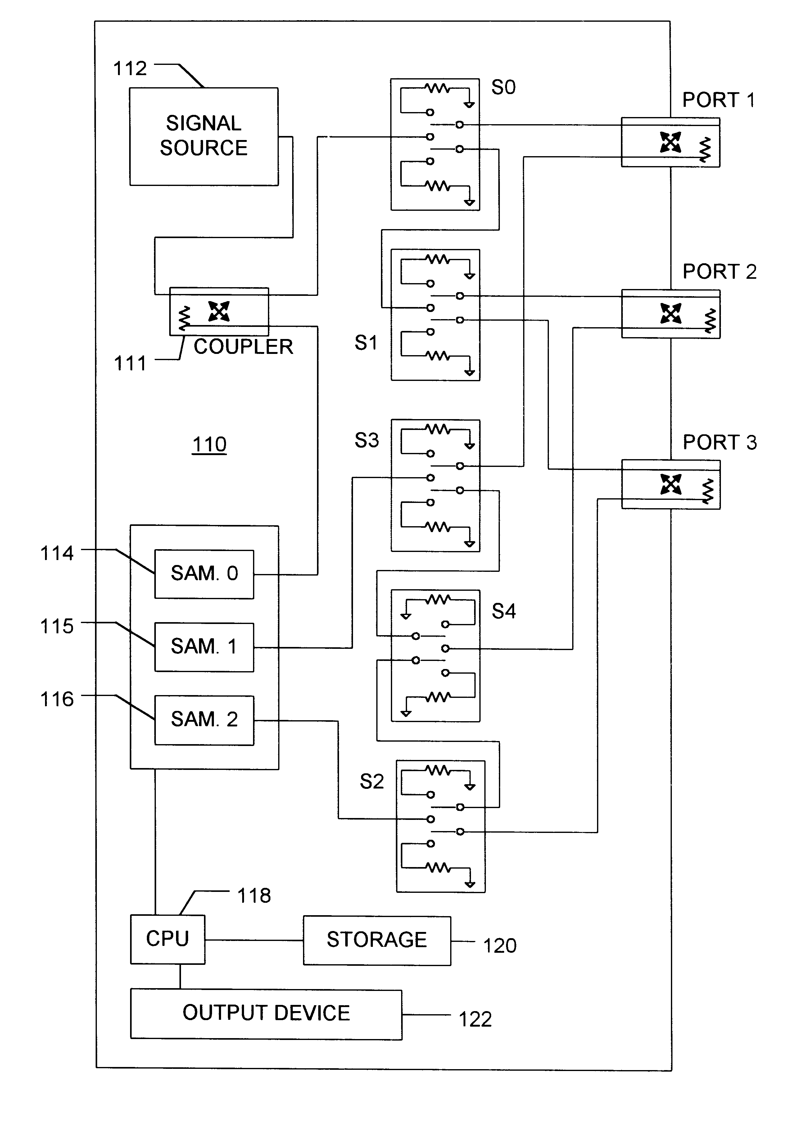
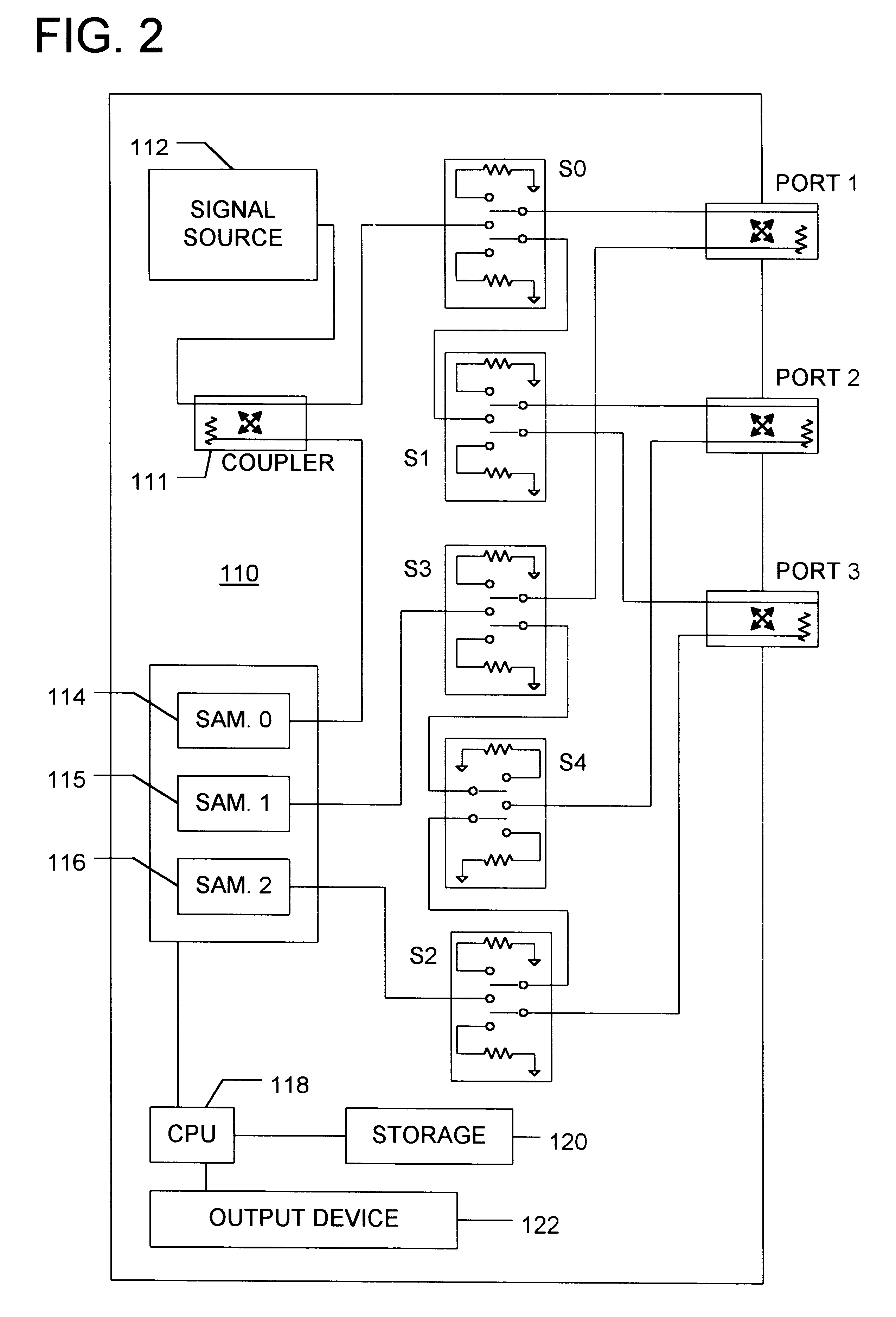
TABLE 3A (CASE 1) Scattering parameter measured Where P = 3 Receiver 1 Receiver 2 Sweep 1 S.sub.11M S.sub.21M Sweep 2 S.sub.22M S.sub.32M Sweep 3 S.sub.33M S.sub.13M

Alternative measurements that may be made are listed in TABLE 3B. The alternative measurements exist because, for any port combination i and j, either S.sub.ij or S.sub.ji may be measured.

TABLE 3B (CASE 2) Scattering parameter measured Where P = 3 Receiver 1 Receiver 2 Sweep 1 S.sub.11M S.sub.31M Sweep 2 S.sub.22M S.sub.12M Sweep 3 S.sub.33M S.sub.23M
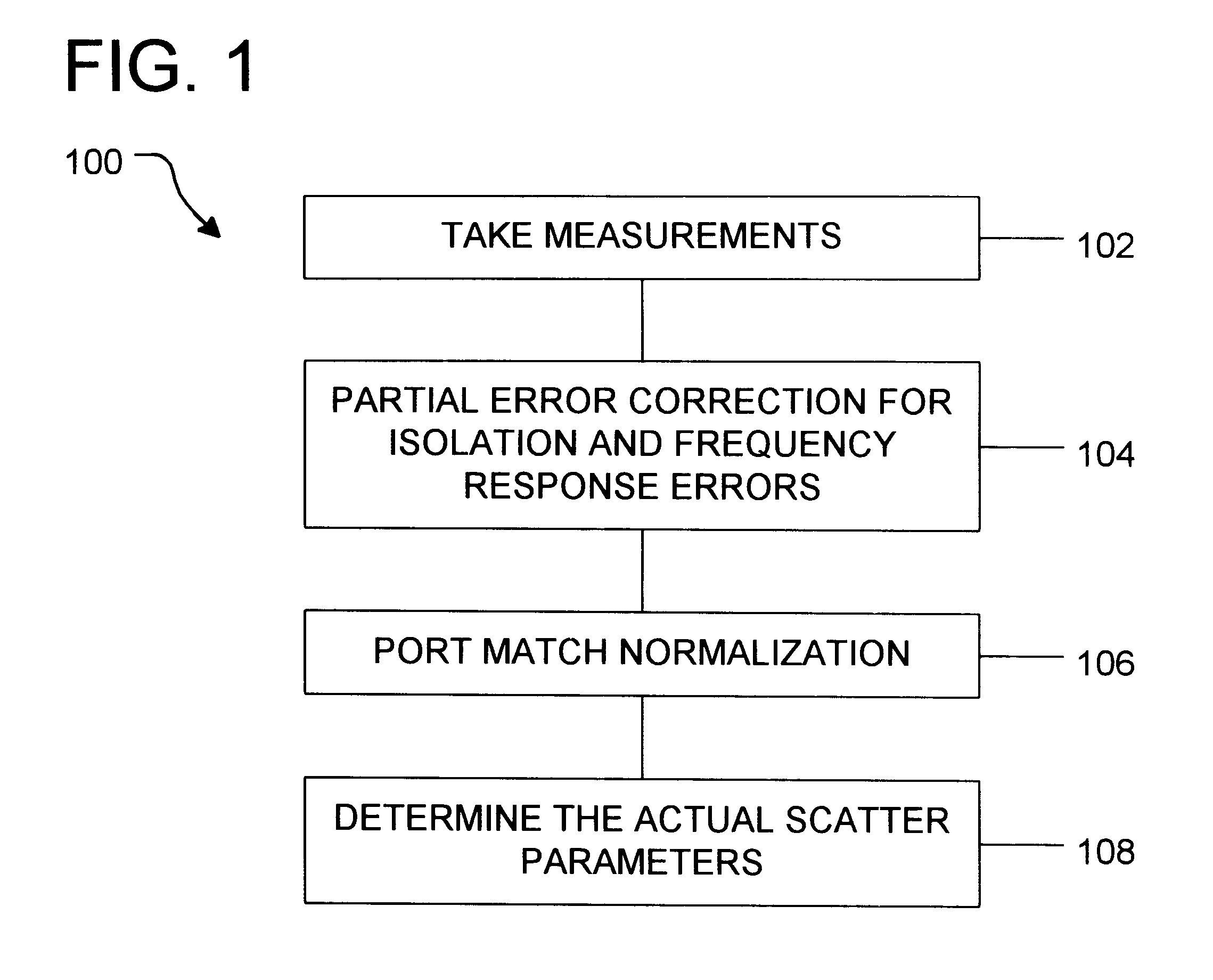
Error Correction

Next, the measured values are partially error corrected to remove isolation errors and frequency response errors introduced by a VNA. Operation 104. Imperfections in network analyzer hardware degrade measurement accuracy. The effect of some hardware imperfections can be characterized and removed from the measurements via vector error correction. Hardware imperfections corrected by this process include isolation errors (directivity for reflection measurements ...


PUM


Abstract

Method and apparatus to determine scattering coefficients for a device under test (DUT) using a vector network analyzer (VNA) is disclosed. Traditionally, for a DUT having P ports, all combinations of reflective and transmission coefficients are measured and calculated. This is true even for reciprocal devices where S.sub.ijA =S.sub.jiA because, during the measurement, the source and load matches vary. However, the present invention teaches that, for reciprocal devices, only one of the two transmission coefficients between a first port and a second port need be measured. Under the inventive technique, error terms are removed from the measured scattering coefficients. Then, the source and the load matches may be normalized to a normalization match value. The normalization process removes the differences of the source and the load matches. Accordingly, for reciprocal devices, only one of two reciprocal transmission coefficients need be measured to determine the transmission coefficients for both directions between the first and the second port. The reduction of the measurement requirement reduces the amount of hardware required for a VNA, time required to characterize a DUT, or both.

Description

BACKGROUNDThe present invention relates to vector network analyzers. More specifically, the present invention relates to the method and apparatus for efficiently measuring scattering parameters of multiport devices in vector network analysis.Vector network analyzers (VNAs) are used to determine the transmission and reflection characteristics of various devices under test (DUTs). A transmission or a reflection characteristic is usually referred to as a scattering parameter S. In order to fully characterize a particular DUT, transmission characteristics and reflection characteristics for all combination of two ports are made. In general, for a P port device, this requires P.sup.2 scattering parameters, or S.sub.ij for each i and j where i goes from 1 to P and j goes from 1 to P. A scattering coefficient is represented as S.sub.ij where S.sub.ij represents reflection coefficient for port i when i=j and transmission coefficient from port j to port i when i.noteq.j. For convenience, addi...

Claims


Application Information

Patent Timeline
IPC IPC(8): G01R27/00G01R27/32H04L69/40G01R27/28
CPCG01R27/32
Inventor BLACKHAM, DAVID VERNON
Owner AGILENT TECH INC
Why Eureka
Try Eureka