Device for maneuvering a shutter or roller-type closure member and process for manufacturing such a closure member

Inactive Publication Date: 2002-06-04
I M B A C
View PDF10 Cites 7 Cited by
  • Summary
  • Abstract
  • Description
  • Claims
  • Application Information

AI Technical Summary

Benefits of technology

The edgings each extend in at least two substantially perpendicular directions. This allows a relative immobilization of the two shells to be obtained by cooperation of shapes of the edgings, parallel to these two directions.
The outer surface of the first edging is provided with elements in relief adapted to coooperate with corresponding elements in relief formed on the inner surface of the second edging for the assembly of the shells. These elements in relief, which may include grooves and ribs of corresponding profiles, allow a sufficient engagement of the edgings to avoid the shells coming apart.
One of the shells comprises a second edging extending in the direction substantially perpendicular to the direction of relative translation of the shells and provided with at least one housing for receiving a stud borne by the other shell. This makes it possible to obtain an additional relative immobilization of the two shells forming the box.
The invention also relates to a mechanism for maneuvering a shutter, roller blind or the like which comprises a strap winding device as described hereinabove. Such a mechanism is more economical and easier to install than known devices.

Problems solved by technology

When this winding device is in mounted position, there remains a slot for connection between these two shells, the width of this slot not being controllable with precision due to the usual manufacturing tolerances for this type of device.
Dirt tends to accumulate in this slot, which is both unaesthetic and potentially pathogenic.
In addition, such a winding device, which is disposed near an opening, is subjected to variations in temperature of considerable amplitude, in particular as a function of its exposure to the sun.
Finally, the production of a hinge requires complex tools and substantially increases the cost price of the box of the known winding device.

Method used


Image

  • Device for maneuvering a shutter or roller-type closure member and process for manufacturing such a closure member
  • Device for maneuvering a shutter or roller-type closure member and process for manufacturing such a closure member
  • Device for maneuvering a shutter or roller-type closure member and process for manufacturing such a closure member

Examples


Embodiment Construction

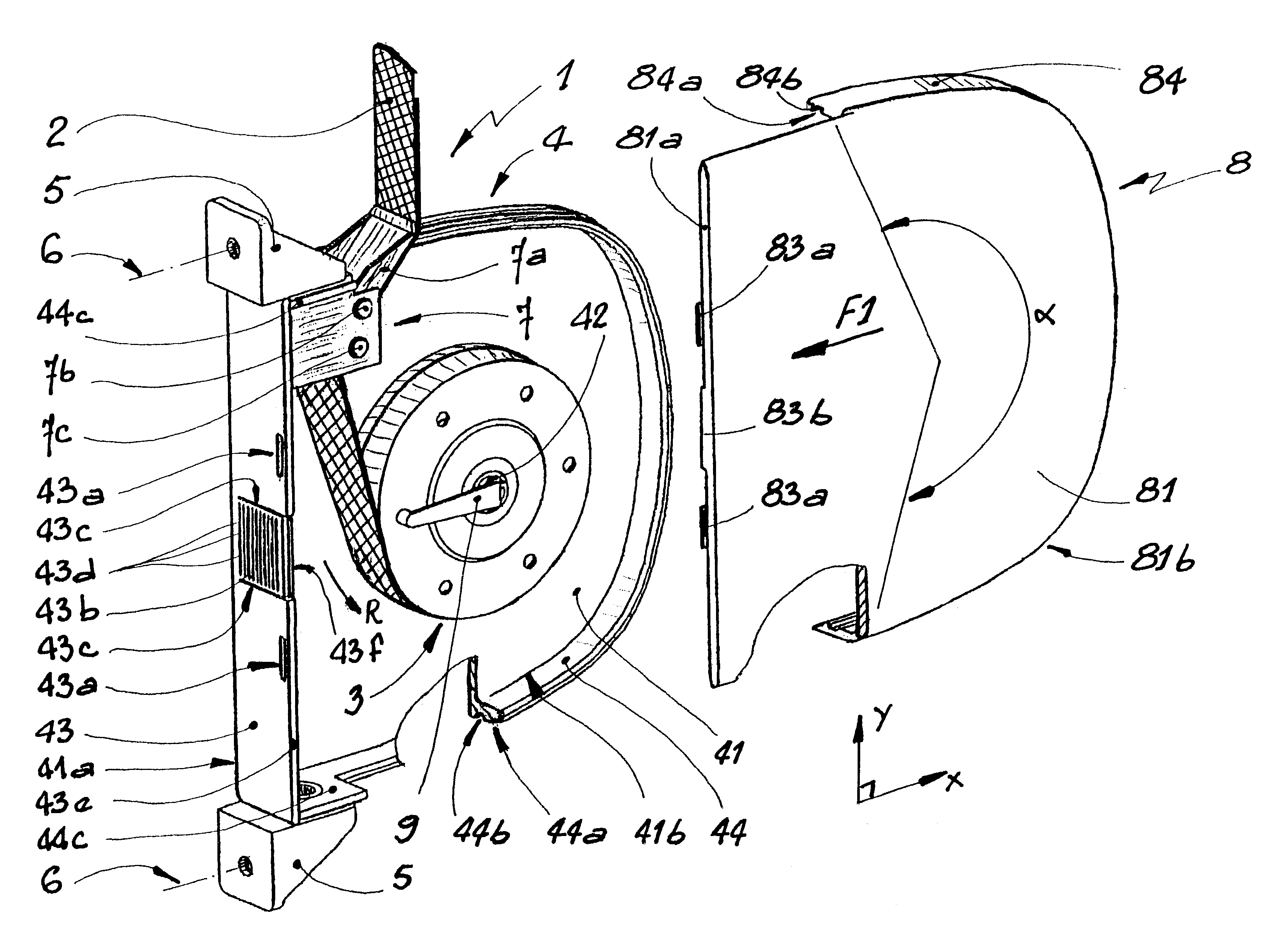
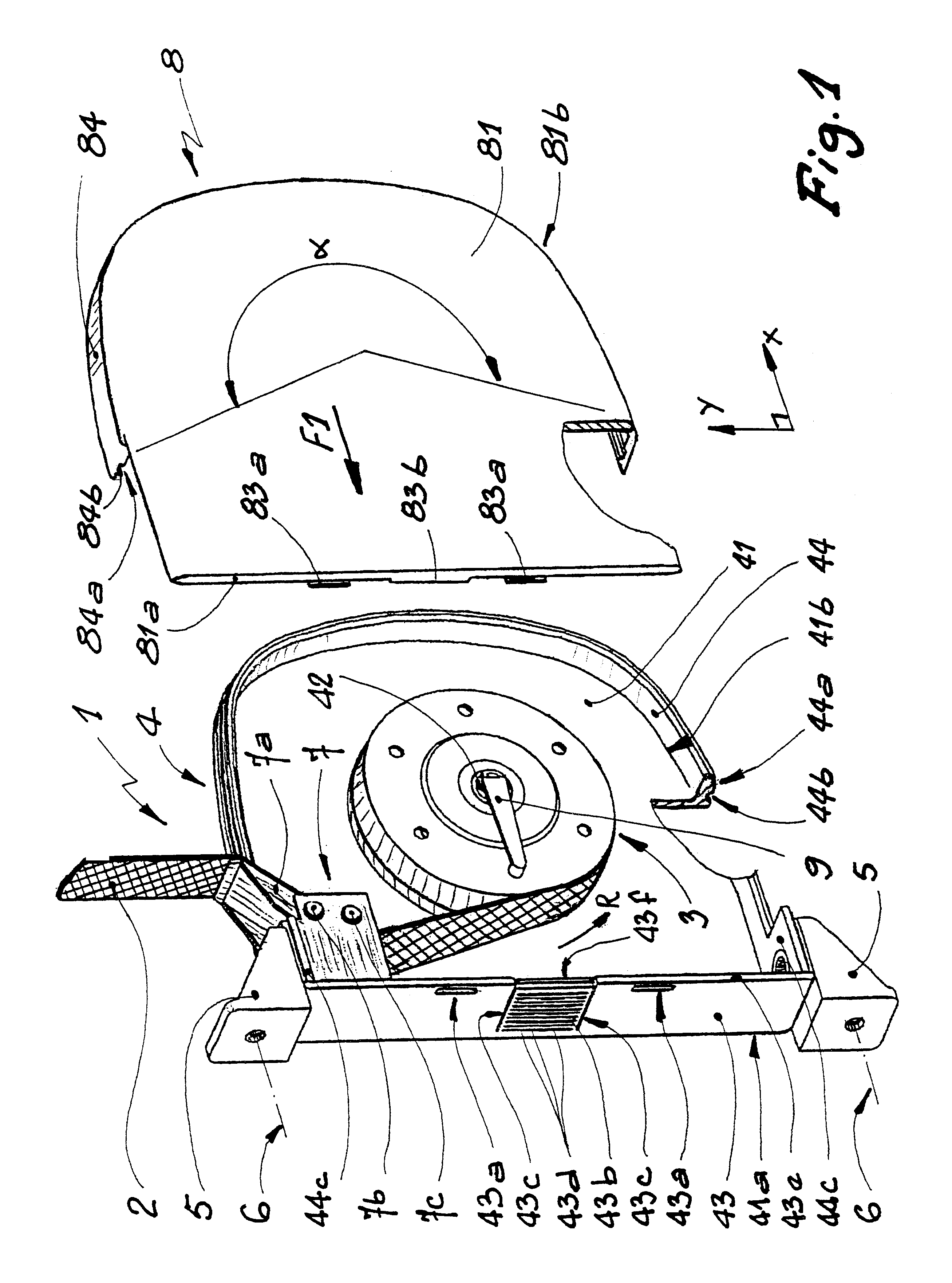
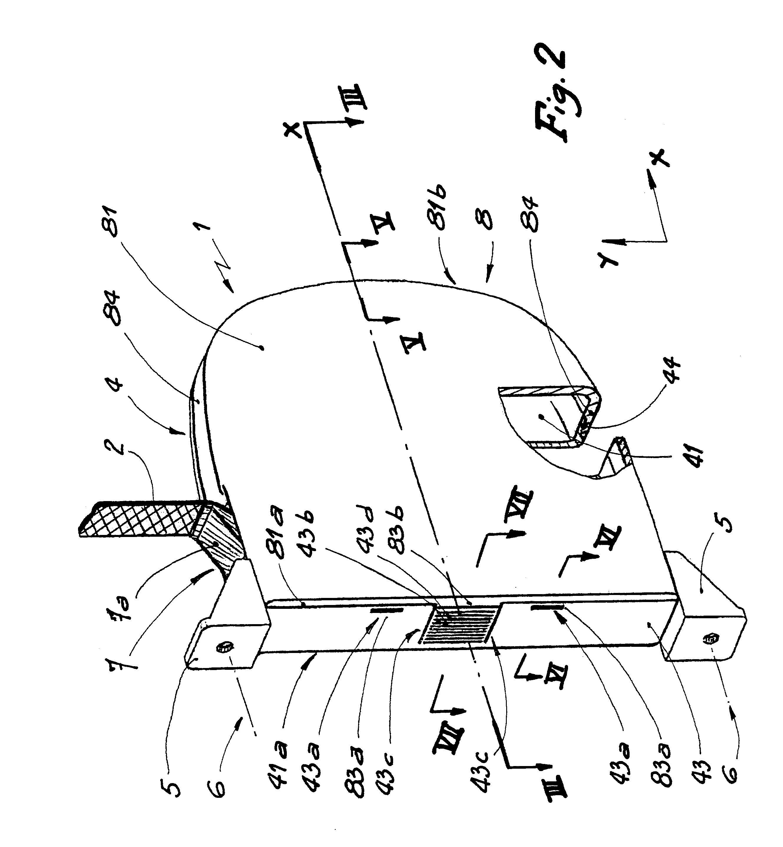
Referring now to the drawings, the winding device 1 shown in the Figures is intended to maintain taut a strap or flexible tie 2 for maneuvering a winding shaft of a shutter, roller blind or equivalent closure member for obturating an opening through which light can pass. A spring box 3 is provided to exert on the strap 2 an elastic effort tending to wind the strap 2 around the box 3 in the direction of arrow R in FIG. 1.

The box 3 is mounted on a shell 4 made of plastics material comprising a principal web 41 in the central part of which there is formed, integral therewith, a shaft 42 for centering the box 3. The web 41 comprises a substantially rectilinear edge 41a and a concave edge 41b whose concavity is turned towards the shaft 42 and the box 3.

At the level of edge 41a, the web 41 extends in a substantially rectilinear edging 43 perpendicular to web 41. Similarly, an edging 44 extends at the level of edge 41b of the web 41, perpendicularly to said web, the edgings 43 and 44 exten...


PUM


Abstract

A device for winding a strap or strip of material for maneuvering a shutter, roller blind or equivalent device comprising a member for winding and tensioning the strap disposed inside a box formed by two shells each including at least one edging extending in a direction substantially perpendicular to a principal web of each shell. The edgings are adapted to be brought into mutual engagement by a relative translation in a direction substantially parallel to the respective principal webs of the shells, in a configuration where an edging of a first shell is covered by an edging of a second shell.

Description

The present invention relates to a strap winding device, to a mechanism for maneuvering a shutter, roller blind or the like comprising such a winding device, and to a process for manufacturing such a winding device.DESCRIPTION OF THE RELATED ARTIt is known to use a belt, strap or any other flexible tie to maneuver a shutter or roller blind and, more generally, for any device comprising a shutter adapted to be selectively wound on a shaft in order to obturate, or not, an opening such as a window or door of a building.In order to avoid such a belt or strap hanging down towards the ground, in particular when the shutter is in wound configuration, it is provided to arrange a strap winding device near such an opening, this device comprising a member for tensioning this strap by automatic winding inside the winding device. For example, EP-A-0 812 795 discloses a strap winding device comprising a spring box disposed inside a body formed by two shells articulated around a hinge and provided...

Claims


Application Information

Patent Timeline
IPC IPC(8): E06B9/78E06B9/56
CPCE06B9/78E06B2009/785
Inventor CATTANEO, RINO
Owner I M B A C
Why Eureka
Try Eureka