
Fluid containment for laboratory containers

a technology for laboratory containers and liquid media, applied in the field of culture plates or dishes, can solve the problems of reducing the volume of liquid media and biological materials, affecting the filtration separation of biological materials, and exceeding the height of the side wall, so as to achieve efficient stacking of culture dish assemblies

Active Publication Date: 2008-11-11
CORNING INC
View PDF35 Cites 2 Cited by
  • Summary
  • Abstract
  • Description
  • Claims
  • Application Information

AI Technical Summary

Benefits of technology

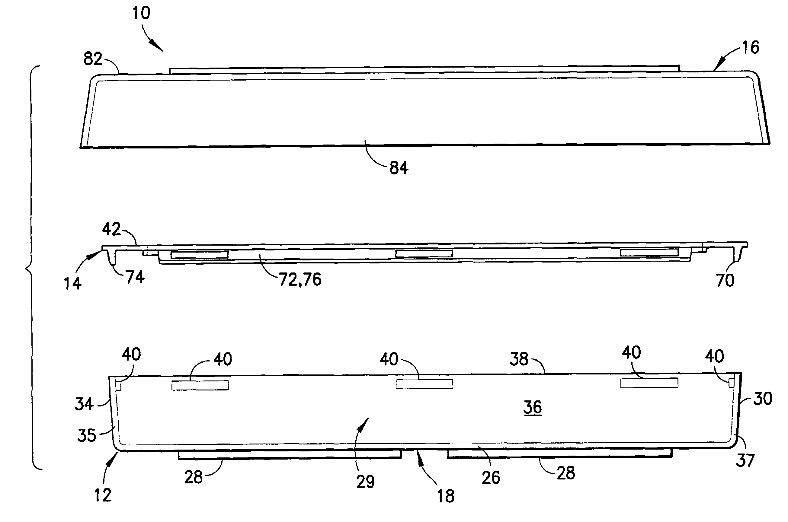
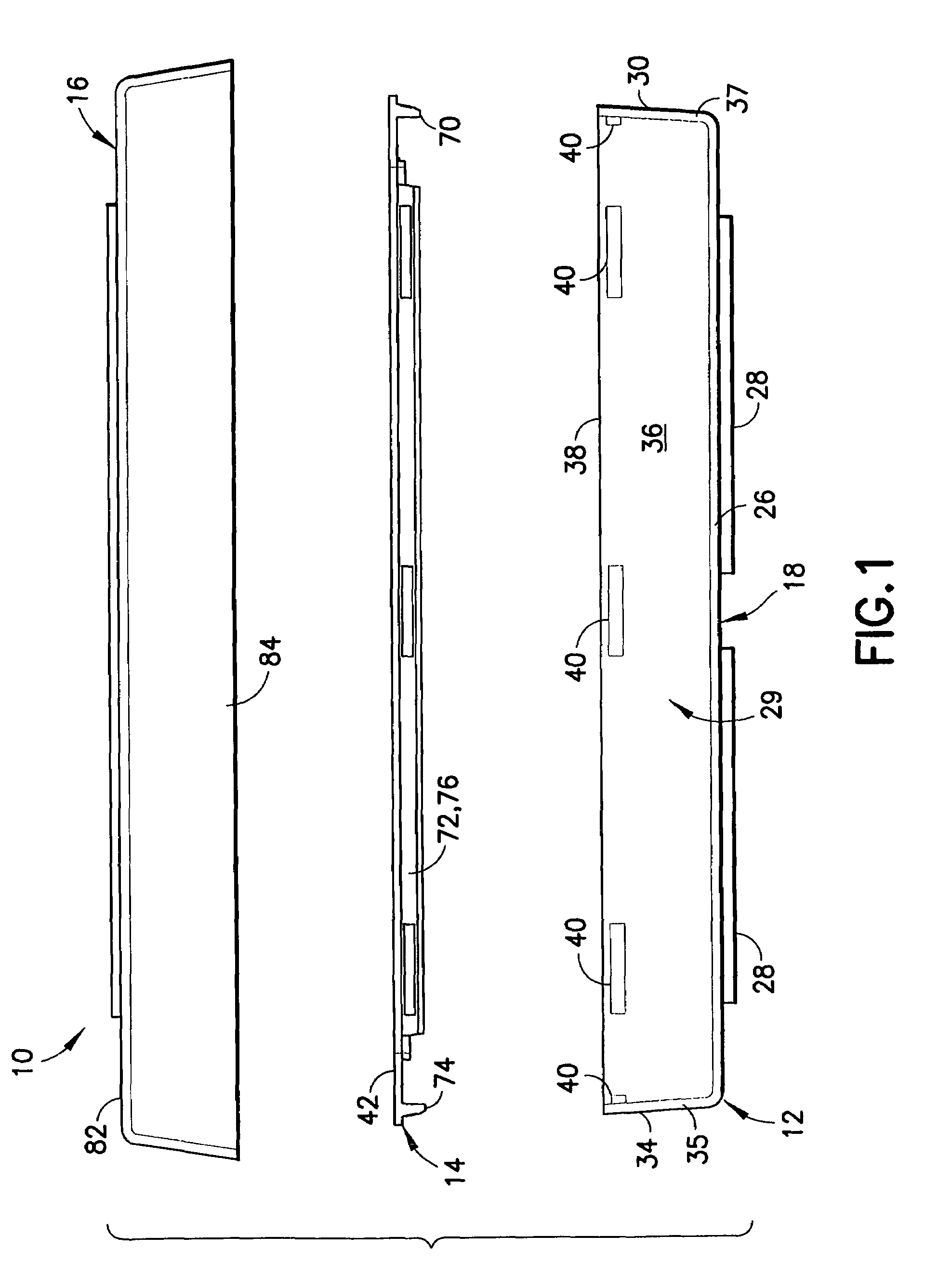
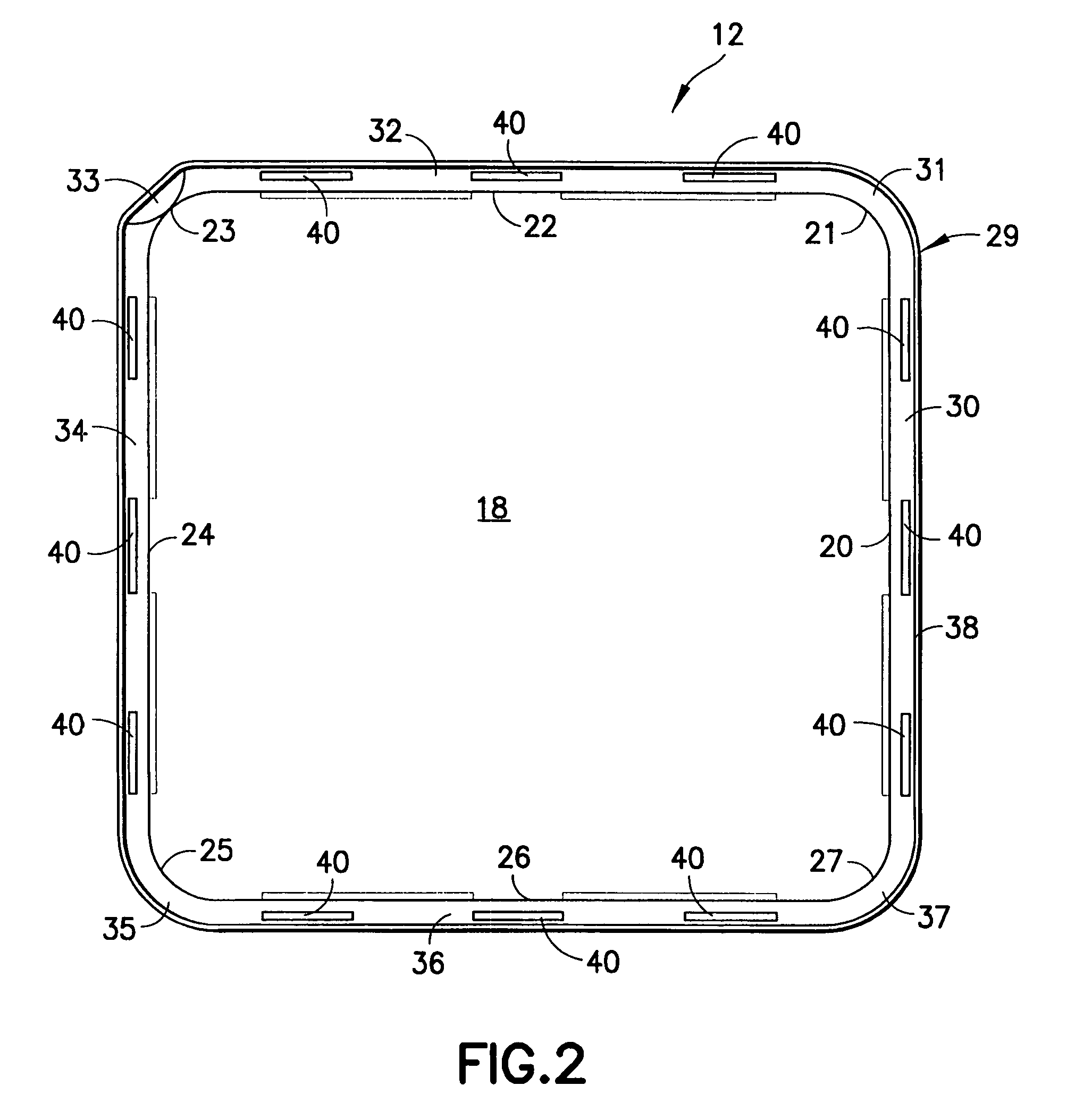
[0011]The invention is a culture dish assembly. The assembly includes a substantially square culture dish unitarily formed from a rigid transparent plastic material. The culture dish includes a bottom wall, a side wall enclosure extending unitarily from the bottom wall and an open top. The bottom wall is substantially planar and substantially square, but may include rounded corners. The dimensions of the bottom wall may vary from one laboratory application to another. For example, the bottom wall may have an area of approximately 500 cm2. A plurality of short support walls may extend down from the lower surface of the bottom wall to support the bottom wall in spaced relationship to a supporting surface and to permit efficient stacking of culture dish assemblies.
[0015]The splash guard may further include two opposed pairs of peripheral engagement flanges that extend down a short distance from the top wall of the splash guard at locations spaced inwardly from the respective straight side edges of the outer periphery. The engagement flanges are disposed to engage inner peripheral surface areas of the planar panels on the side wall enclosure of the culture dish. The engagement flanges of the splash guard may further include spaced apart elongate wall mounts that are disposed to snap into engagement with the respective splash guard mounts on the inner surfaces of the planar panels when the top wall of the splash guard seats on the top edge of the side wall enclosure. The engagement of the wall mounts with the splash guard mounts provides sufficient interference to provide an audible and tactile indication of proper seating of the splash guard on the side wall enclosure and to prevent inadvertent separation of the splash guard from the side wall enclosure.
[0018]The cover further includes a peripheral skirt that extends down from the outer periphery of the top wall. The skirt may be flared outwardly at further locations from the top wall to facilitate molding and to facilitate nesting of the cover over the subassembly of the culture dish and splash guard. The length of the peripheral skirt from the top wall is less than the length of the side wall enclosure from the bottom wall of the culture dish. Thus, the bottom of the skirt will not impede complete seating of the cover on the culture dish when the culture dish is supported on a planar surface.
[0020]The splash guard may require periodic separation from the culture dish for a more thorough access to culture growth in the dish. As noted above, the wall mounts of the engagement flanges of the splash guard engage the splash guard mounts on the inner surfaces of the planar panels of the culture dish. This engagement is sufficient to hold the splash guard in position and to provide a tactile and audible indication of proper positioning. This engagement also can slightly complicate removal of the splash guard from the culture dish. Removal of the splash guard from the culture dish can be facilitated by providing at least one lift element on the splash guard to facilitate separation of the splash guard from the culture dish. For example, the outer periphery of the frame-shaped top wall may be formed with at least one tab projecting outwardly a sufficient distance to project beyond the side wall enclosure of the culture dish. The tab can be engaged digitally to facilitate separation of the splash guard from the culture dish. A plurality of such removal tabs may be provided, and most preferably a tab is provided on each of the straight side edges on the outer periphery of the planar rectangular frame-shaped top wall of the splash guard.
[0022]In still a further alternate, a pull handle may be formed on the upper surface of the frame-shaped top wall of the splash guard. The pull handle can be connected to the frame-shaped top wall by a living hinge so that the pull handle can be rotated between a substantially upright position and a substantially low profile condition substantially adjacent the top surface of the frame-shaped top wall. The handle can be rotated in to the upright position to facilitate engagement between a thumb and forefinger or by a laboratory tool so that the splash guard can be lifted easily from the culture dish. Alternatively, the handle can be rotated about the living hinge and into substantially face-to-face engagement with the frame-shaped top wall to provide a relatively low profile. The provision of the handle and / or the provision of cut-outs or finger slots on the inner periphery of the top wall instead of the above-described pull handle permits a splash guard that can nest slightly into the open top defined by the side wall enclosure of the culture dish. The amount of nesting of the splash guard into the open top defined by the side wall enclosure can be limited due to the slight outward flaring of the side wall enclosure that is provided to facilitate molding of the culture dish. This option enables the assembly of the culture dish and splash guard to have a low profile that does not exceed the overall height of the culture dish. Additionally, this nesting of the splash guard partly into the open top of the side wall enclosure can provide an alternate arrangement for sealing the splash guard to the side wall enclosure. For example, the splash guard can be formed with a gasket that extends around the outer periphery of the frame-shaped top wall of the splash guard to provide a hermetic seal between the side wall enclosure of the culture dish and the splash guard.

Problems solved by technology

As noted above, the side walls of a culture dish are very short, and hence even a small wave in the liquid media can cause the liquid media to splash out of the culture dish.
The wave effects generated in such a large culture dish easily can exceed the height of the side wall, and hence significant amounts of liquid media can splash from the culture dish.
Splashing reduces the volume of liquid media and biological materials in the culture dish, and hence can affect the laboratory analysis.
Additionally, splashing of liquid media and other biological materials can cause contamination in the laboratory.
For example, liquid media in one culture dish can inadvertently splash into an adjacent culture dish.
However, these unitary structures are difficult to mold.
Splash guards that telescope over the side wall are undesirable because they add to the overall dimensions required for the culture dish.
This spacial arrangement of culture dishes result in substantial dead space between the points of tangency.
Hence, circular culture dishes result in an inefficient use of space.
It is difficult to ensure uniform orientation of round culture dishes after the culture dishes have been moved for sampling or replenishment of the liquid growth media.
Additionally, it is difficult to measure variations in the growth characteristics of cultures at various locations across the bottom wall of the culture dish.
Still further, it is difficult to pour liquid media from a round culture dish in view of the relatively large radius of curvature on the cylindrical side wall.
However, square culture dishes are not conducive to receiving a separately mountable splash guard.
However, it is difficult to achieve uniform forces along such a rectilinear array of interengaged surfaces, and stress concentrations are likely to exist.
The existence of non-uniform engagement forces around the peripheries of a square splash guard can complicate the mounting of the splash guard and can damage either the splash guard or the side walls.
Additionally, gaps may exist between mating surfaces of the square splash guard and the side wall.
Thus, although square culture dishes offer advantages over cylindrical culture dishes, the square culture dishes are not well suited to the splash guards that have been employed with round culture dishes.

Method used


Image

  • Fluid containment for laboratory containers
  • Fluid containment for laboratory containers
  • Fluid containment for laboratory containers

Examples


second embodiment

[0055]a splash guard in accordance with the subject invention is identified generally by the numeral 114 in FIG. 8. Splash guard 114 is very similar to splash guard 14 described above and illustrated most clearly in FIGS. 3 and 4. Elements of splash guard 114 that are identical to splash guard 14 merely are identified by the same reference numerals herein, and a repeated description is not provided. Splash guard 114 differs from splash guard 14 in two significant respects. In particular, splash guard 114 includes a top wall 142 with an outer periphery 144. Outer periphery 144 has substantially straight outer side edges 150, 152, 154 and 156 and arcuate corners 151, 153, 155 and 157 as shown in FIG. 8. Substantially straight edges 150, 152, 154, and 156 are dimensioned and configured to substantially register with the outer periphery of top edge 38 of side wall enclosure 29 on culture dish 12. However, substantially straight edges 150, 152, 154 and 156 are characterized further by li...

third embodiment

[0057]FIGS. 12-15 show a culture dish assembly 210 in accordance with the subject invention. The culture dish assembly 210 includes a rectangular culture dish 212 that is very similar to culture dish 12 described and illustrated above. More particularly, culture dish 212 includes a bottom wall 218 and a side wall enclosure 229. However, side wall enclosure 229 of culture dish 212 does not include elongate projections comparable to elongate projections 40 on culture dish 12. Rather, interior surfaces of side wall enclosure 229 may be substantially smooth between top edge 238 of side wall enclosure 229 and bottom wall 218. Importantly, however, side wall enclosure 229 flares outwardly from bottom wall 218 to facilitate molding.

[0058]Culture dish assembly 210 further includes a splash guard 214 with a frame-shaped wall 242. Frame-shaped wall 242 includes an outer periphery 244 dimensioned to nest partly within side wall enclosure 229 of culture dish 212. Thus, outer periphery 244 of fr...

fourth embodiment

[0060]a culture dish assembly in accordance with the subject invention is identified by the numeral 310 in FIG. 16. Culture dish assembly 310 includes a culture dish 312 that is substantially identical to culture dish 212 described above and illustrated in FIGS. 12 and 13. Culture dish assembly 310 further includes a splash guard 314 with a frame-shaped generally planar wall 342. Frame-shaped wall 342 has an outer periphery 344 and an inner periphery 346. Outer periphery 344 is dimensionally comparable to outer periphery 244 of splash guard 214 described above and illustrated in FIGS. 12-15. Inner periphery 346, however, is provided with a plurality of finger slots 350 that are dimensioned to be engaged by fingers or by laboratory equipment for pulling splash guard 314 out of culture dish 312.


PUM

PropertyMeasurementUnit
Distanceaaaaaaaaaa

Abstract

A culture dish assembly includes a polygonal culture dish with a bottom wall and a side wall enclosure formed by a plurality of generally planar panels joined consecutively to one another by non-planar corners. The side wall enclosure includes a generally planar top edge. Inner surface regions of a plurality of the planar panels are formed with a plurality of projections or recesses that are spaced from one another and spaced from the corners. A splash guard includes engagement flanges disposed for nesting with inner peripheral surface regions of the panels of the side wall enclosure. The engagement flanges include projections or recesses disposed for releasably engaging the projections or recesses on the side wall enclosure to hold the splash guard on the culture dish without creating stress concentrations in the corners.

Description

[0001]This application claims the benefit of U.S. Provisional Application Ser. No. 60 / 458,925, filed on Mar. 31, 2003.BACKGROUND OF THE INVENTION[0002]1. Field of the Invention[0003]The invention relates to culture plates or dishes with a guard for preventing inadvertent splashing of fluid from the culture plate or dish.[0004]2. Description of the Related Art[0005]Culture plates or dishes are used for culturing cells, bacteria or other biological materials. The typical culture dish is formed from a transparent plastic and has a substantially flat bottom wall, a short side wall enclosure that extends up from the bottom wall and an open top. The bottom wall typically is circular and the side wall typically is cylindrical. However, rectangular culture dishes are known.[0006]A liquid growth media is placed in the culture dish and a small sample of the cells, bacteria or other biological materials are placed in the liquid growth material. A transparent cover then may be placed over the o...

Claims


Application Information

Patent Timeline
IPC IPC(8): C12M1/22B01L3/00B65D25/00C12M1/00
CPCB01L3/508C12M23/10C12M23/24B01L2200/141B01L2300/041B01L2300/046B01L2300/0809
Inventor TRAMMEL, II, HAROLD W.HALL, JOHN P.
Owner CORNING INC
Learn More