Device for air cleaning

a technology for air cleaning and vacuuming equipment, which is applied in the direction of transportable electrostatic units, external electric electrostatic separators, heating types, etc., can solve the problems of difficult cleaning of air, unwieldy practice, and high demand for clean air for individuals

Inactive Publication Date: 2002-06-04
EURUS AIRTECH
View PDF11 Cites 93 Cited by
  • Summary
  • Abstract
  • Description
  • Claims
  • Application Information

AI Technical Summary

Problems solved by technology

In certain indoor environments, i.e. open-plane offices, individuals having a higher demand of clean air may face problems since it costwise, spacewise or from other reasons may be difficult to clean the air in the entire premises in question to fulfill the demands of said individuals.
If precipitators of such dimensions would be manufactured in a traditional way, e.g. from sheet metal, they would in practice be unwieldy.

Method used


Image

  • Device for air cleaning
  • Device for air cleaning
  • Device for air cleaning

Examples


Embodiment Construction

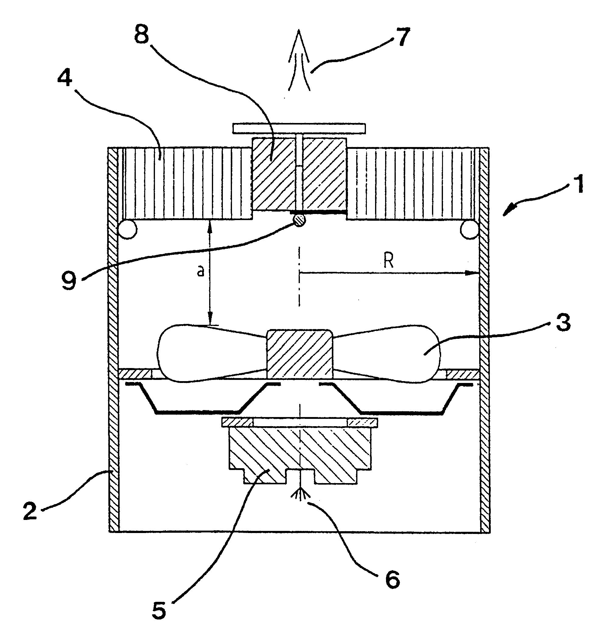
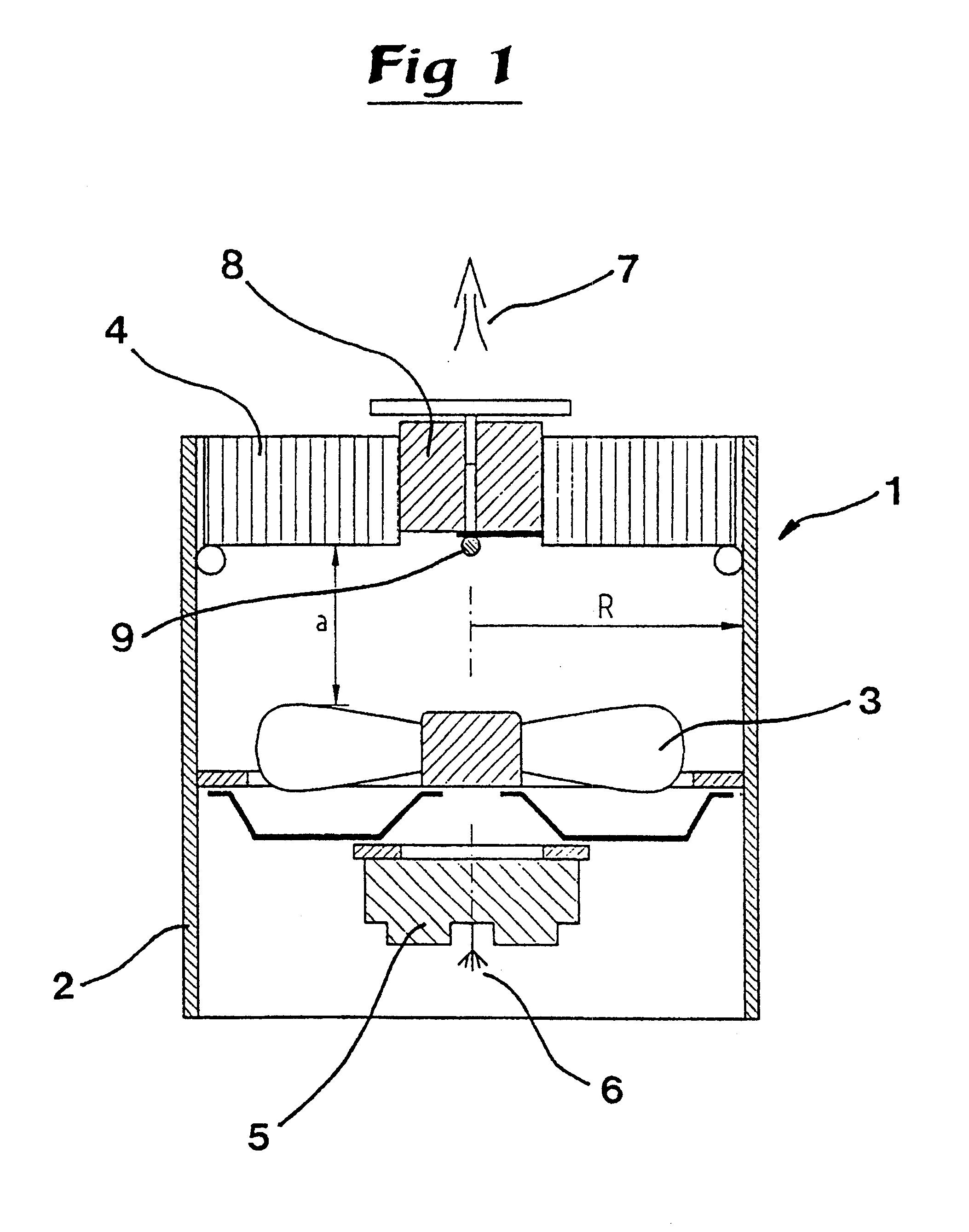
The device 1 shown in FIG. 1 includes a tubular air flow channel 2 having a radius R, an air transporting fan 3, a precipitator 4, a high voltage source 5 and an ionisation electrode 6.

The precipitator 4 is designed in accordance with SE-A-9602211-6, said document being included in this application by way of reference. Thus the precipitator 4 includes two electrode elements in the shape of band-like strips that are wound around a bobbin body and electrically connected with a respective terminal of the high voltage source 5 in the air flow channel 2, said channel 2 having a similar cross section as the precipitator 4. As is apparent from FIG. 1, see the arrow 7 for the air flow direction, the precipitator 4 is arranged downstream the fan 3 in the air flow channel 2.

The precipitator 4 according to SE-A-9602211-6is manufactured from at least two band-like strips, preferably of paper or other high-ohmic (antistatic) material, said strips being wound around a bobbin body 8, see FIG. 1, s...


PUM

PropertyMeasurementUnit
diameteraaaaaaaaaa
air velocityaaaaaaaaaa
axial distanceaaaaaaaaaa

Abstract

The present invention is directed to a device (1;1';1''; 1'''; 1''''; 1''''') for air cleaning, especially from electrically charged particles, the device (1;1';1''; 1'''; 1''''; 1''''') including an air flow channel (2;2';2''; 2'''; 2''''; 2'''''), an air transporting mechanical fan (3;3';3''; 3'''; 3''''; 3'''''), a precipitator (4;4';4''; 4'''; 4''''; 4'''''), a high voltage source (5;5';5''; 5'''; 5''''; 5'''''), the precipitator (4;4';4''; 4'''; 4''''; 4''''') including two band-like electrode elements that are wound several times around an axis or bobbin body (7;7';7''; 7'''; 7''''; 7'''''), a gap distance being present between adjacent electrode elements, respective electrode elements being electrically connected with each terminal of the high voltage source (5;5';5''; 5'''; 5''''; 5'''''), characterized in that the precipitator (4;4';4''; 4'''; 4''''; 4''''') is arranged downstream of the fan (3;3';3''; 3'''; 3''''; 3''''').

Description

This application is a national stage application of International Application No. PCT / SE98 / 00398, filed Mar. 5, 1998.PRIOR ARTDue to the increasing number of individuals having allergical / asthmatic problems the environment debate has been focused around the indoor environment, the central point being the quality of the indoor air. In connection with this focusing the use of so called freestanding air cleaners has increased simultaneously as their function has developed from providing isolated contributions to constituting a complement to an existing ventilation system. However, in order to achieve a complete acceptance as a complement to or part of ventilating measures these devices must fulfill high technical demands, they must be easy to handle and last but not least they must be adaptable to a certain indoor environment through their design and their choice of colour scheme.In certain indoor environments, i.e. open-plane offices, individuals having a higher demand of clean air ma...

Claims


Application Information

Patent Timeline
Patent Type & Authority Patents(United States)
IPC IPC(8): B03C3/00B03C3/32F24F3/16
CPCF24F3/166B03C3/32B03C3/155B03C3/06B03C3/12B03C3/49B03C3/60B03C2201/08B03C2201/10F24F8/192Y02A50/20
Inventor LORETH, ANDRZEJ
Owner EURUS AIRTECH
Why Eureka
Try Eureka