Level indicator

a level indicator and level sensor technology, applied in the field of level sensors, can solve problems such as the difficulty of sealing such a device with respect to external influences

Inactive Publication Date: 2002-06-11
CONTINENTAL AUTOMOTIVE GMBH
View PDF3 Cites 48 Cited by
  • Summary
  • Abstract
  • Description
  • Claims
  • Application Information

AI Technical Summary

Problems solved by technology

It is difficult to seal such a device with respect to external influences.

Method used


Image

  • Level indicator
  • Level indicator
  • Level indicator

Examples


Embodiment Construction

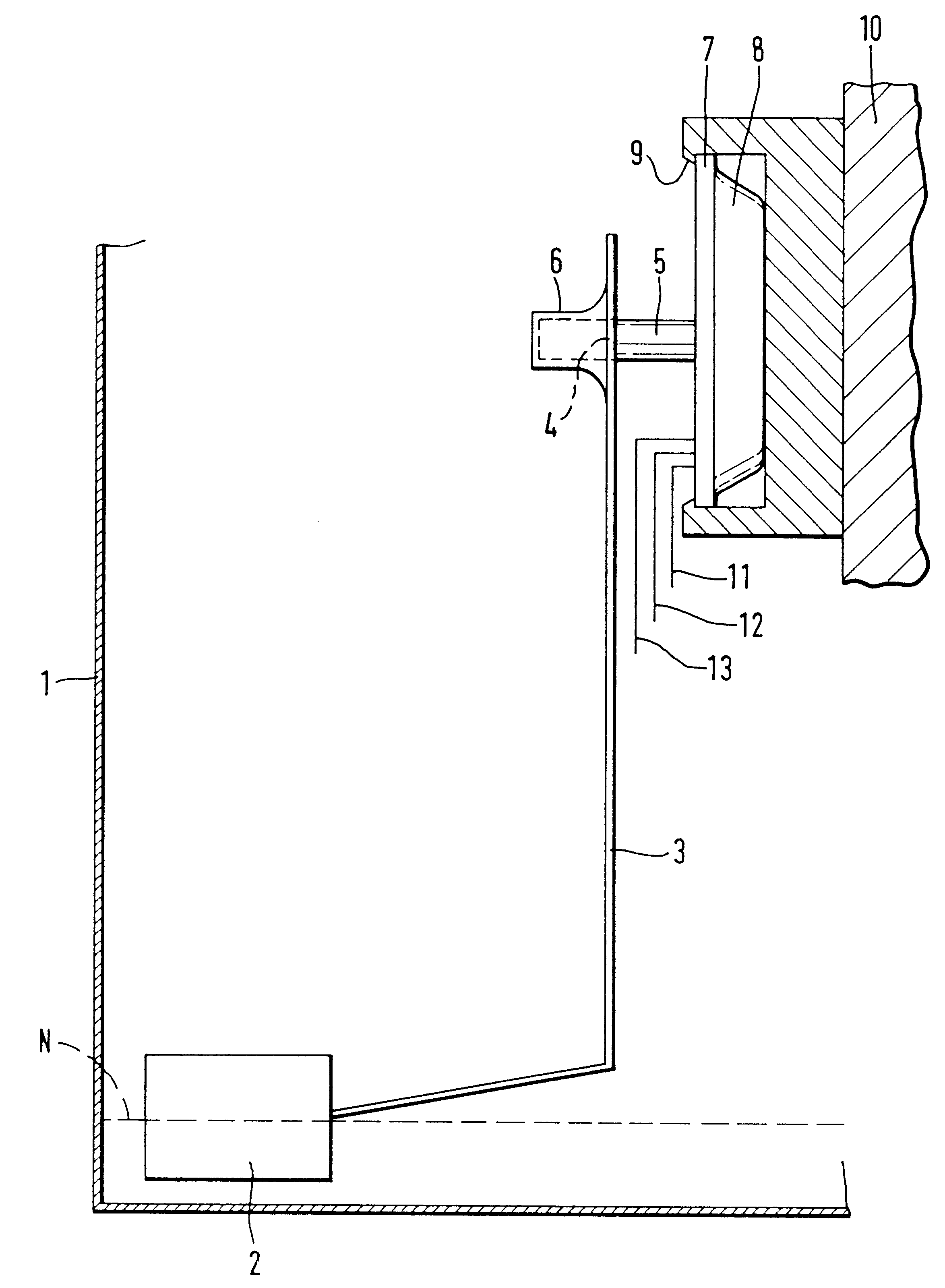
FIG. 1 diagrammatically depicts the arrangement of the level sensor according to the invention in a splash pot 1. The level N formed by the fuel is indicated by dashed lines.

A float 2 is connected to a float lever 3. At the opposite end from the float 2, this float lever 3 has an opening 4, in which a magnet 5 is arranged in a force-fitting manner in a sleeve 6. The magnet 5 which projects out of the opening 4 is preloaded toward the outside of the housing 7, 8 by means of the float lever 3, so that the magnet 5 can move with gentle contact depending on the position of the float 2.

The housing 7, 8 comprises an insulating substrate 7 which is tightly soldered, welded or adhesively bonded to a housing cover 8. Substrate 7 and the housing cover 8 are made from material with identical or similar coefficients of thermal expansion. The housing 7, 8 is attached by means of a clip-together device 9 arranged on a sensor support 10. The sensor support 10 is itself fixed to the splash pot 1, b...


PUM


Abstract

A fluid level sensor that is particularly useful in fluid fuel tanks of motor vehicles wherein a resistor network is arranged on a fixed support and it is possible to generate an output signal from the resistor network which corresponds to the position of a float member. The level sensor has particularly low wear and is inexpensive to produce with a contact structure for the resistor network that operates through interaction of a magnetic member is moved by the float and can be deflected such that an electrical connection is dependent on the position of the float.

Description

1. Field of the InventionThe invention relates to a level sensor, in particular for the fuel tank of a motor vehicle, in which a resistor network is arranged on a fixed support, it being possible to pick off an output signal on the resistor network, which signal corresponds to the position of a float which follows the level of a liquids.2. Description of the Related ArtLevel sensors of this nature are known for use in motor-vehicle fuel tanks in connection with delivery units. In the installed state, such delivery units are supported on the base of the vehicle fuel tank. The level sensor is in this case arranged directly on the splash pot or is arranged on a sensor support which in turn is attached to the splash pot. A slide potentiometer of the level sensor is actuated by a float, vial a float lever, as a function of the level in the fuel tank. The changing level allows a corresponding electrical signal to be picked up at the slide potentiometer.WO 94 / 27119 A1 has disclosed a level...

Claims


Application Information

Patent Timeline
Patent Type & Authority Patents(United States)
IPC IPC(8): B60K15/077F02B77/08G01F23/30G01F23/62G01F23/38H01C10/00H01C10/16H01H36/00H01H36/02B60K15/03B60K15/06G01F23/36F02D33/00F02M37/00
CPCB60K15/077F02B77/08H01H36/02G01F23/38G01F23/62H01C10/16B60K15/061B60K2015/03217B60K2015/03467F02M37/0082F02D33/003G01D5/165G01F23/363
Inventor GIER, LOTHARWALLRAFEN, WERNER
Owner CONTINENTAL AUTOMOTIVE GMBH
Why Eureka
Try Eureka