Aerosol spray gun

a technology of aerosol and spray gun, which is applied in the direction of combustion process, burner, combustion type, etc., can solve the problem of large volume of air supplied to the outlet of patterning air

Inactive Publication Date: 2002-06-11
CARLISLE FLUID TECH RANSBURG JAPAN KK
View PDF3 Cites 102 Cited by
  • Summary
  • Abstract
  • Description
  • Claims
  • Application Information

AI Technical Summary

Benefits of technology

It is another object of the present invention to provide an aerosol spray gun which can be comprised of a reduced number of components compared with the prior art embodiments.

Problems solved by technology

When the trigger is fully squeezed, however, such movement of the trigger is transmitted to the movable valve element via the coupling means, and the movable valve element is moved away from the valve seat to remain the throttle valve mechanism open, resulting in a large volume of air being supplied to the outlet of the patterning air.
Thus, while the trigger is fully squeezed, the paint jetted out is large in both volume and pattern, and this results in the paint being sprayed in a large pattern.

Method used


Image

  • Aerosol spray gun
  • Aerosol spray gun
  • Aerosol spray gun

Examples


Embodiment Construction

Preferred embodiments of the present invention will be described below in detail in conjunction with the accompanying drawings.

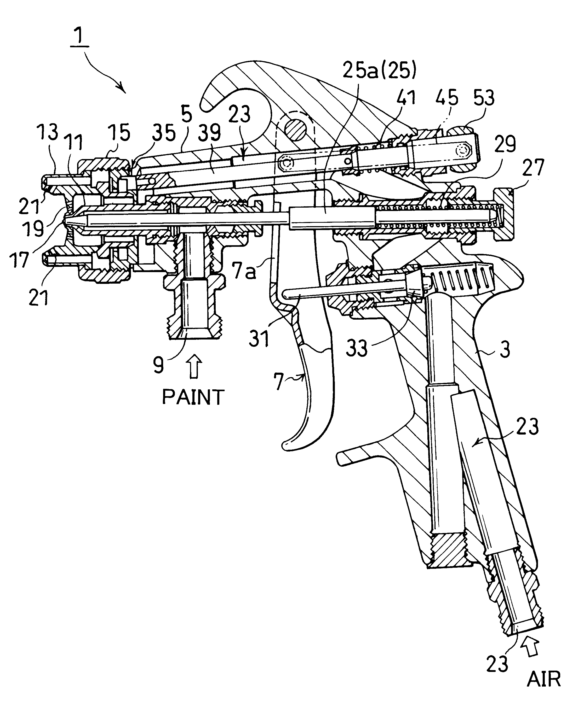
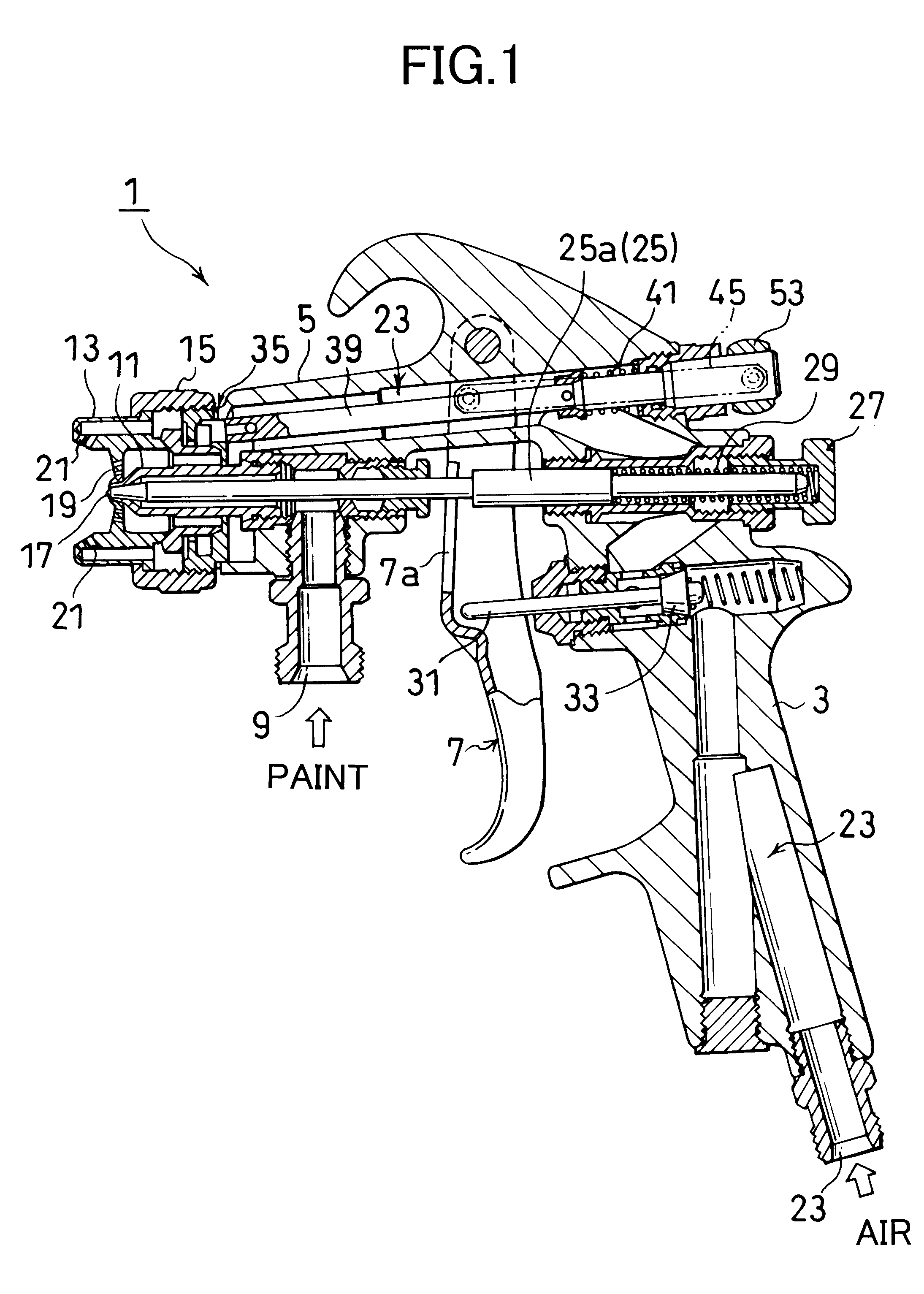
FIG. 1 is a vertical cross sectional view showing an embodiment of an aerosol spray gun. An aerosol spray gun 1 is a hand-held gun outlined as follows: Similar to the prior art, the aerosol spray gun 1 has a handle 3 and a barrel 5, and an operator (not shown), who holds the handle 3, squeezes a trigger 7 so that pain introduced from a paint introducing port 9 in the middle of the barrel 5 can be hit by atomizing air from the tip of the barrel 5 and transformed into mist to be jetted out ahead in a paint spray stream.

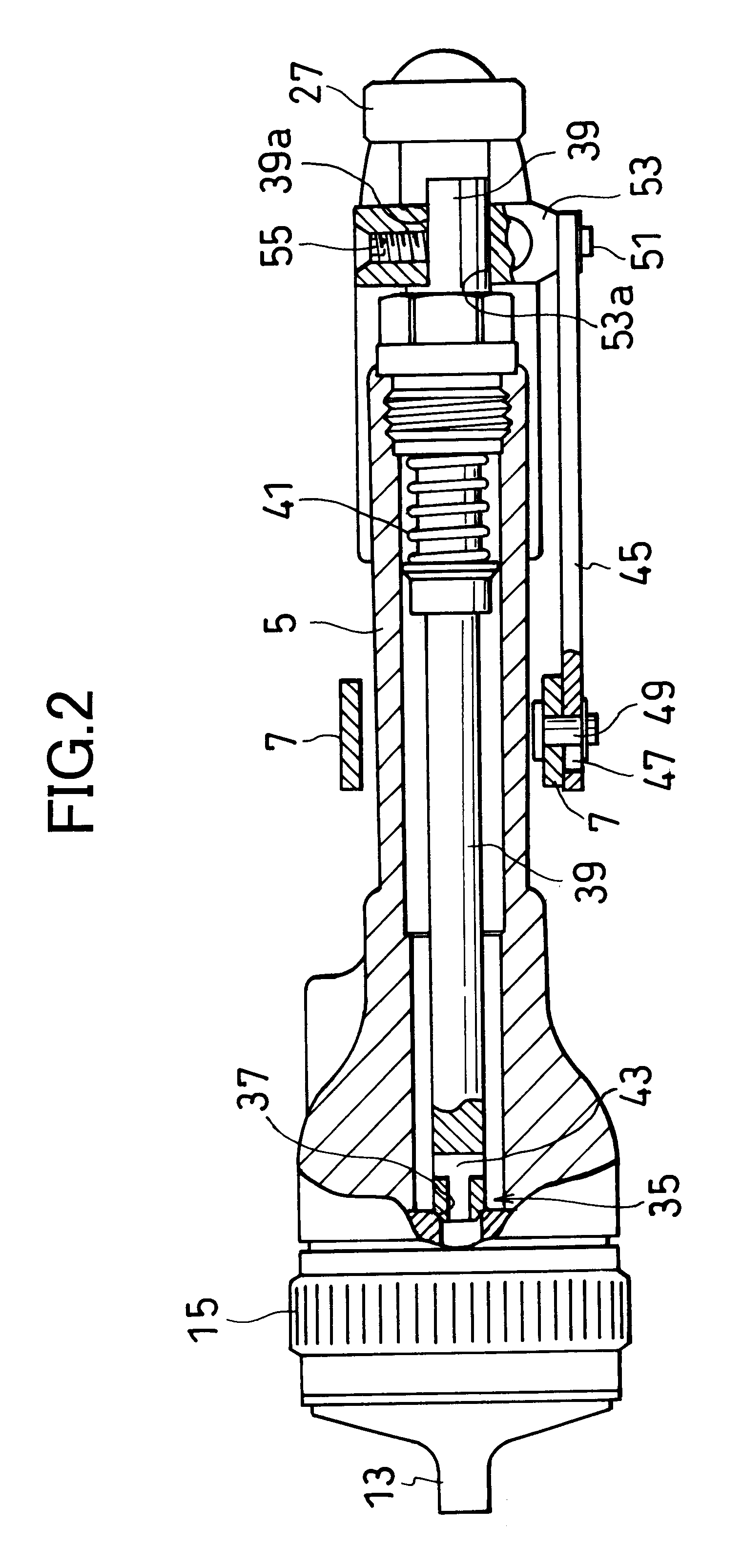
The aerosol spray gun 1 will now be further detailed, and the barrel 5 has its tip removably loaded with a paint nozzle 11 and an air cap 13 via a fixture ring 15, both of which make up a spraying head. The paint nozzle 11 has a paint spraying aperture 17 at its center. The air cap 13 is provided with an atomizing air outlet 19 positioned close ...


PUM


Abstract

An aerosol spray gun used selectively in two spraying modes of small and large patterns is provided. The aerosol spray gun has a throttle valve, an air duct, and a coupling link. The throttle valve has an internal air duct for supplying pressurized air to a patterning air outlet which shapes a paint spraying stream jetted out from the aerosol spray gun, and has a movable valve element to which a compressed spring applies force to open the valve. The air duct created at the tip of the movable valve element supplies a small volume of air from the internal air duct to the patterning air outlet while the movable valve element seats on a valve seat. The coupling link, coupling the movable valve element to the trigger, has an elongated hole to disconnect the trigger from the movable valve element without cooperative relation between them from an initial stage where an operator begins to squeeze the trigger to an intermediate stage before the operator fully squeezes the trigger.

Description

1. (Field of the Invention)The present invention relates to an aerosol spay gun used for spraying paint on an object.2. (Prior Art)In general, an aerosol spray gun transforms liquid paint into mist or aerosol to jet the aerosol paint stream ahead and directs patterning air to the aerosol paint stream to shape it as desired.Official Gazette of Japanese Patent Laid-Open No. H2-102755 discloses a hand-held aerosol spay gun capable of altering mass of the spraying pattern. Such an aerosol spray gun has an air flow rate regulating valves in air flow paths through which pressurized air is supplied toward a spraying air outlet and a pattering air outlet close to a nozzle of the gun, and the air flow rate regulating valves cooperative with a trigger serves to supply the spraying air outlet and patterning air outlet with air by an amount corresponding to an amount of squeezing of the trigger, or namely, an amount of ejected paint.More specifically, the air flow rate regulating valves in the ...

Claims


Application Information

Patent Timeline
Patent Type & Authority Patents(United States)
IPC IPC(8): B05B7/02B05B7/12B05B7/08
CPCB05B7/1209B05B7/12B05B7/0815B05B7/1245B05B7/0838
Inventor KANEKO, SHUZOHASHIMOTO, SHIGEFUMI
Owner CARLISLE FLUID TECH RANSBURG JAPAN KK
Why Eureka
Try Eureka