Low pressure drop, multi-slit virtual impactor

a virtual impactor and low pressure drop technology, applied in the field of virtual impactors, can solve the problems of particle not being able being caught by the obstacle, and being unable to deflect around the obstacle, so as to achieve low pressure drop, easy construction, and high fluid flow

Inactive Publication Date: 2002-06-11
LAWRENCE LIVERMORE NAT SECURITY LLC
View PDF22 Cites 33 Cited by
  • Summary
  • Abstract
  • Description
  • Claims
  • Application Information

AI Technical Summary

Benefits of technology

An additional aspect of the present invention is to provide a micro-machined virtual impactor system having high fluid flow and low pressure drop.
A

Problems solved by technology

If an obstacle is placed in the path of the fluid stream, the fluid is deflected around the obstacle while the particles are less able to deflect arou

Method used


Image

  • Low pressure drop, multi-slit virtual impactor
  • Low pressure drop, multi-slit virtual impactor
  • Low pressure drop, multi-slit virtual impactor

Examples


Embodiment Construction

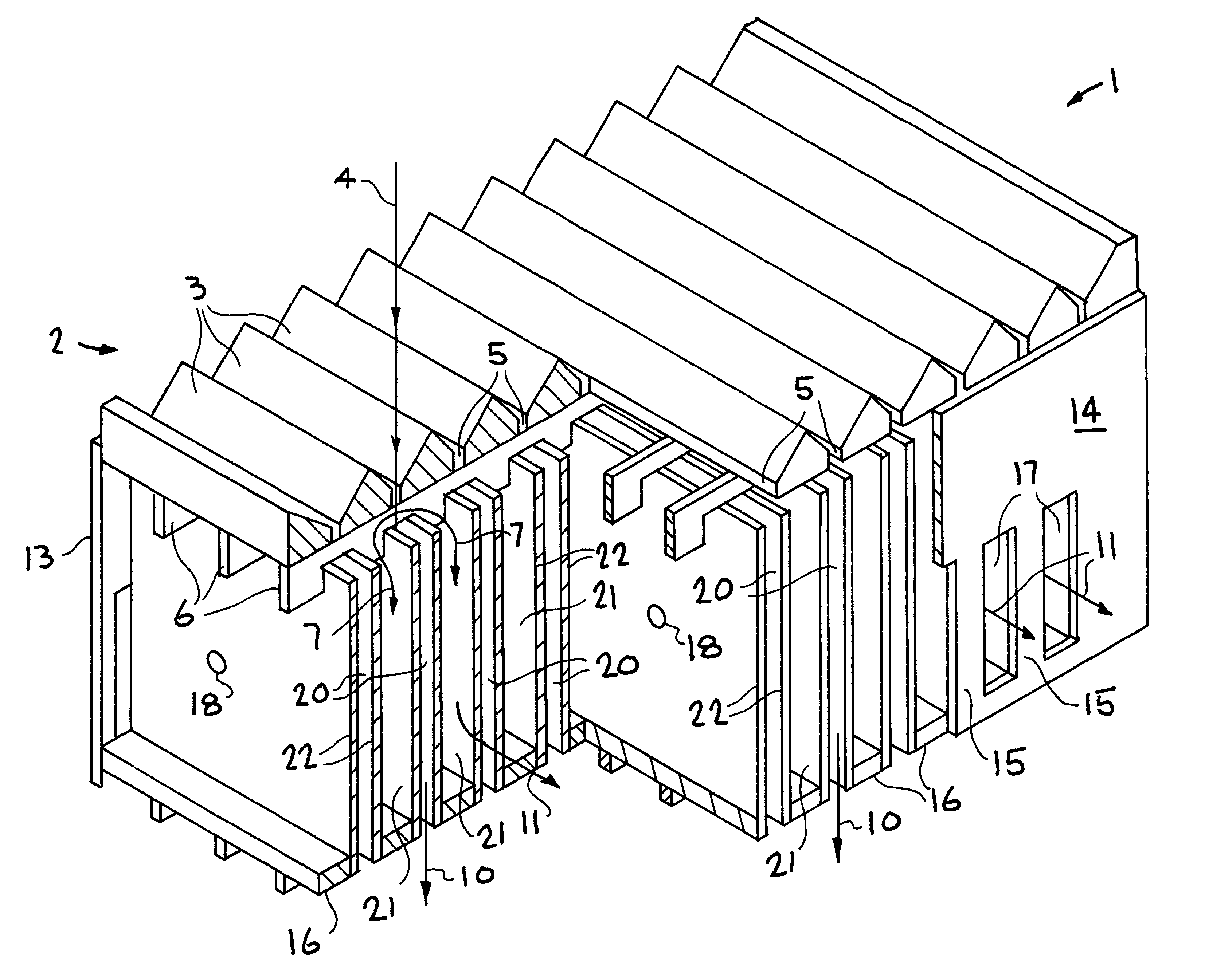
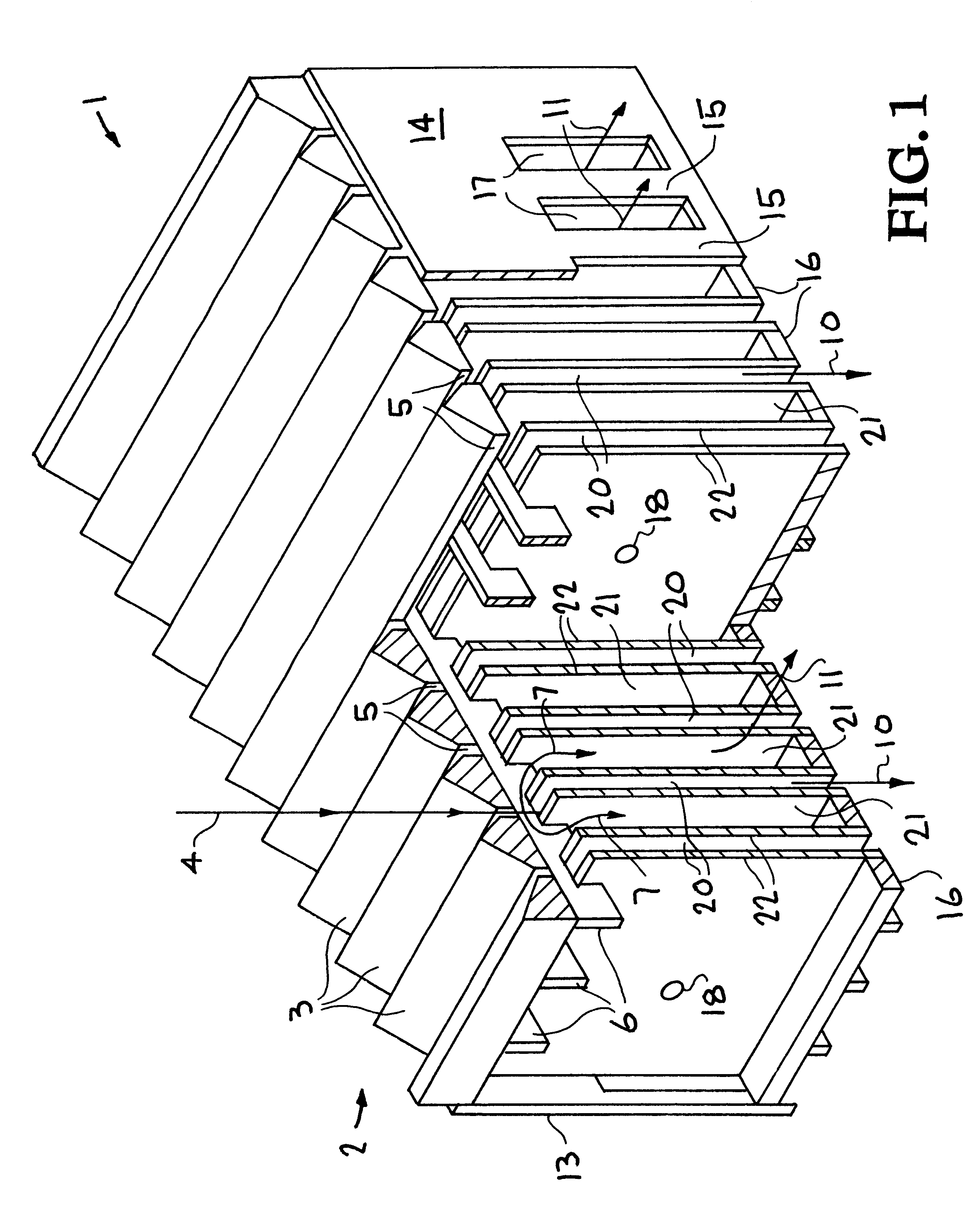
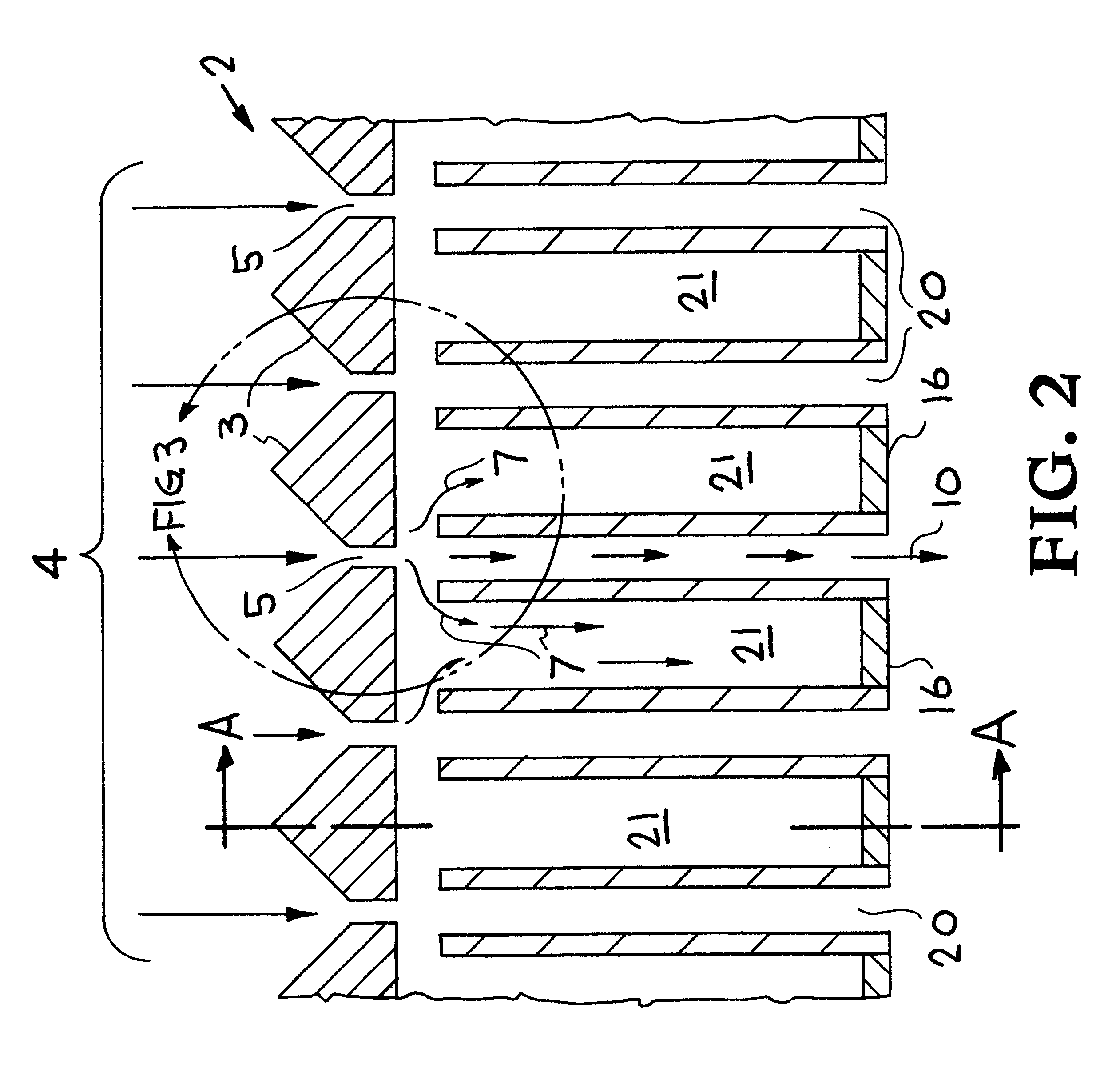
Referring now to the drawings, and more particularly to FIGS. 1, 2, 3, and 4, an embodiment of a multi-slit virtual impactor is described to illustrate the virtual impactor system of the present invention. Virtual impactor consists of multiple accelerating nozzle assembly 2, multiple receiving chambers 20, and multiple exhaust chambers 21. The virtual impactor divides a particle containing gas flow into a small flow component carrying particles essentially greater than a predetermined size and a large flow component carrying particles essentially less than the predetermined size. The virtual impactor system of the present invention can operate using fluids other than gas, for example liquids.

As shown in FIGS. 1, 2, and 3, the inlet gas flow 4 containing particles approaches the multiple accelerating nozzle assembly 2 and is focused on the nozzle slits 5 by the beveled sides 3 which provide a smooth transition to the narrow slit nozzles 5. The purpose of the accelerating nozzles 5 is...


PUM

PropertyMeasurementUnit
Lengthaaaaaaaaaa
Lengthaaaaaaaaaa
Fractionaaaaaaaaaa

Abstract

Fluid flow is directed into a multiplicity of slit nozzles positioned so that the fluid flow is directed into a gap between the nozzles and (a) a number of receiving chambers and (b) a number of exhaust chambers. The nozzles and chambers are select so that the fluid flow will be separated into a first particle flow component with larger and a second particle flow component with the smaller particles.

Description

BACKGROUND OF THE INVENTION1. Field of EndeavorThe present invention relates to inertial classifiers, and more particularly, to a virtual impactor. The virtual impactor system of the present invention will separate a fluid stream into a first particle flow component containing particles essentially greater than a selected size and a second particle flow component containing particles essentially smaller than the selected size.2. State of TechnologyImpactors belong to a class of instruments called inertial classifiers, which separate particles in a fluid stream based on the inertia of particles. In general these instruments operate by forcing a change in the direction of the fluid stream containing the particles. Because of the particles inertia the particles cannot follow the fluid stream. If an obstacle is placed in the path of the fluid stream, the fluid is deflected around the obstacle while the particles are less able to deflect around the obstacle. If the particle inertia excee...

Claims


Application Information

Patent Timeline
IPC IPC(8): B01D45/00B01D45/04
CPCB01D45/04
Inventor BERGMAN, WERNER
Owner LAWRENCE LIVERMORE NAT SECURITY LLC
Why Eureka
Try Eureka