
Tape cartridge-holding mechanism and tape printing apparatus including the same

Inactive Publication Date: 2002-06-18
SEIKO EPSON CORP +1
View PDF10 Cites 122 Cited by
  • Summary
  • Abstract
  • Description
  • Claims
  • Application Information

AI Technical Summary

Benefits of technology

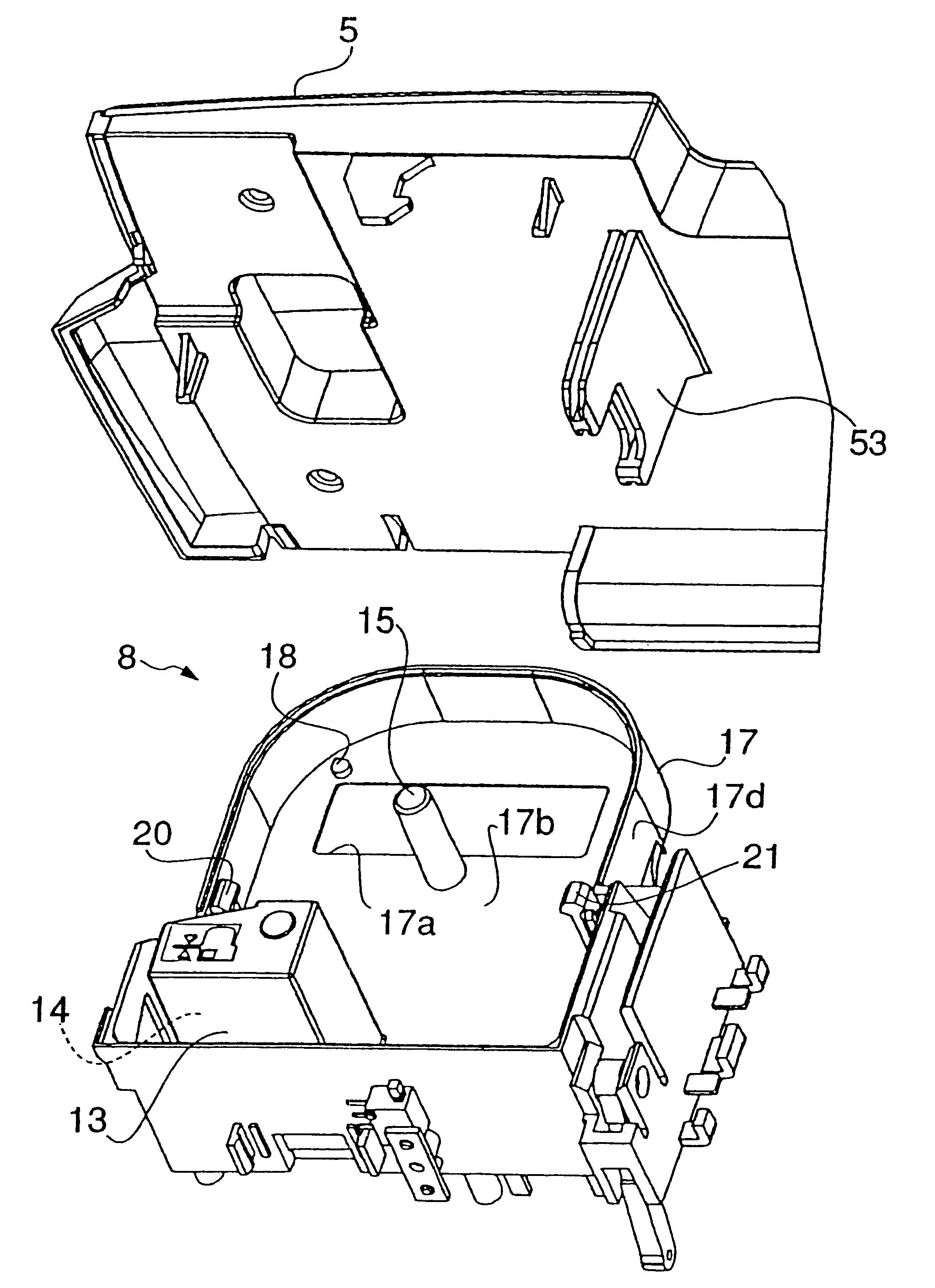
According to this construction, when the lid is closed after a tape cartridge having been mounted in the cartridge compartment, the urging mechanism urges the holding nails in the direction of sandwiching the tape cartridge. As a result, in a state of the lid being closed, the holding nails sandwich the tape cartridge therebetween such that they firmly press the tape cartridge against the bottom surface of the cartridge compartment. On the other hand, in a state of the lid being open, the urging of the holding nails by the urging mechanism is canceled, so that it is possible to mount or remove the tape cartridge in or from the cartridge compartment easily by a small force.
According to this construction, since cam action of the cam surface between the operating piece and the urging member is utilized, it is possible to press on the holding nail by the mechanism having a simple construction.
According to this construction, the holding nail can be urged stably by the resilient element, which makes it possible to stably hold a tape cartridge in spite of an error or tolerance of width of the tape cartridge in the direction of being sandwiched.
According to this construction, since the tape printing apparatus is capable of immovably holding a tape cartridge in the cartridge compartment, it is possible to effectively prevent a tape from being advanced in an inclined state or jammed. Further, it is possible to mount and remove the tape cartridge by a small force.

Problems solved by technology

The tape printing apparatus in which the tape cartridge is held in the cartridge compartment by the conventional holding nails suffers from a problem that if the spring force of each holding nail is set to be small, the tape cartridge is lifted when the printing tape is rolled out, which causes the tape to be advanced in an inclined state or jammed.
Particularly when the holding nails are made of resin and integrally formed with the compartment casing, long-term use of the apparatus can permanently set the holding nails in fatigue, thereby causing a decrease in their spring force.
On the other hand, if the spring force of each holding nail is set to be large, a large force is required to mount and remove a tape cartridge, which makes the mounting / removing of the tape cartridge troublesome.

Method used


Image

  • Tape cartridge-holding mechanism and tape printing apparatus including the same
  • Tape cartridge-holding mechanism and tape printing apparatus including the same
  • Tape cartridge-holding mechanism and tape printing apparatus including the same

Examples


Embodiment Construction

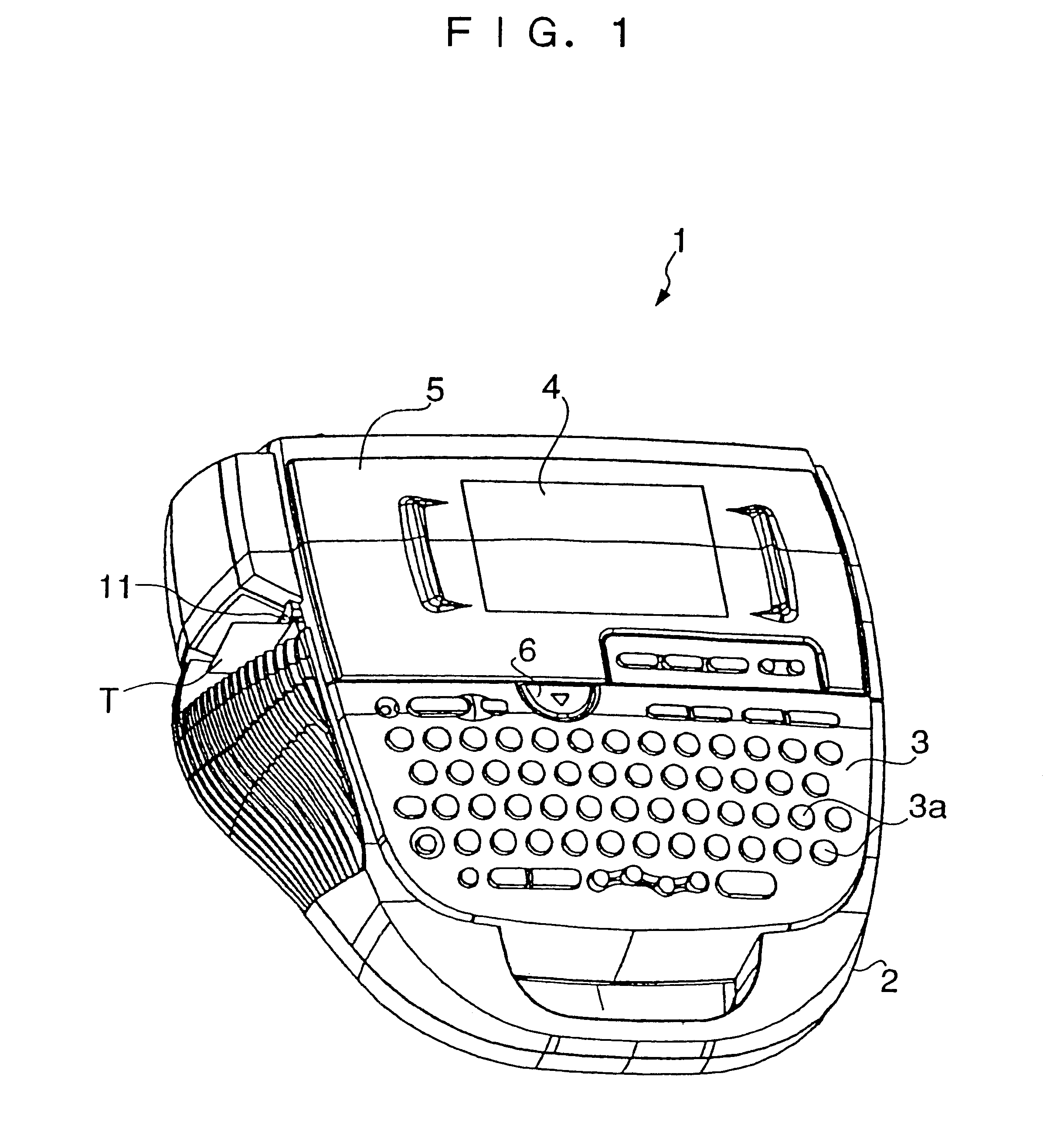
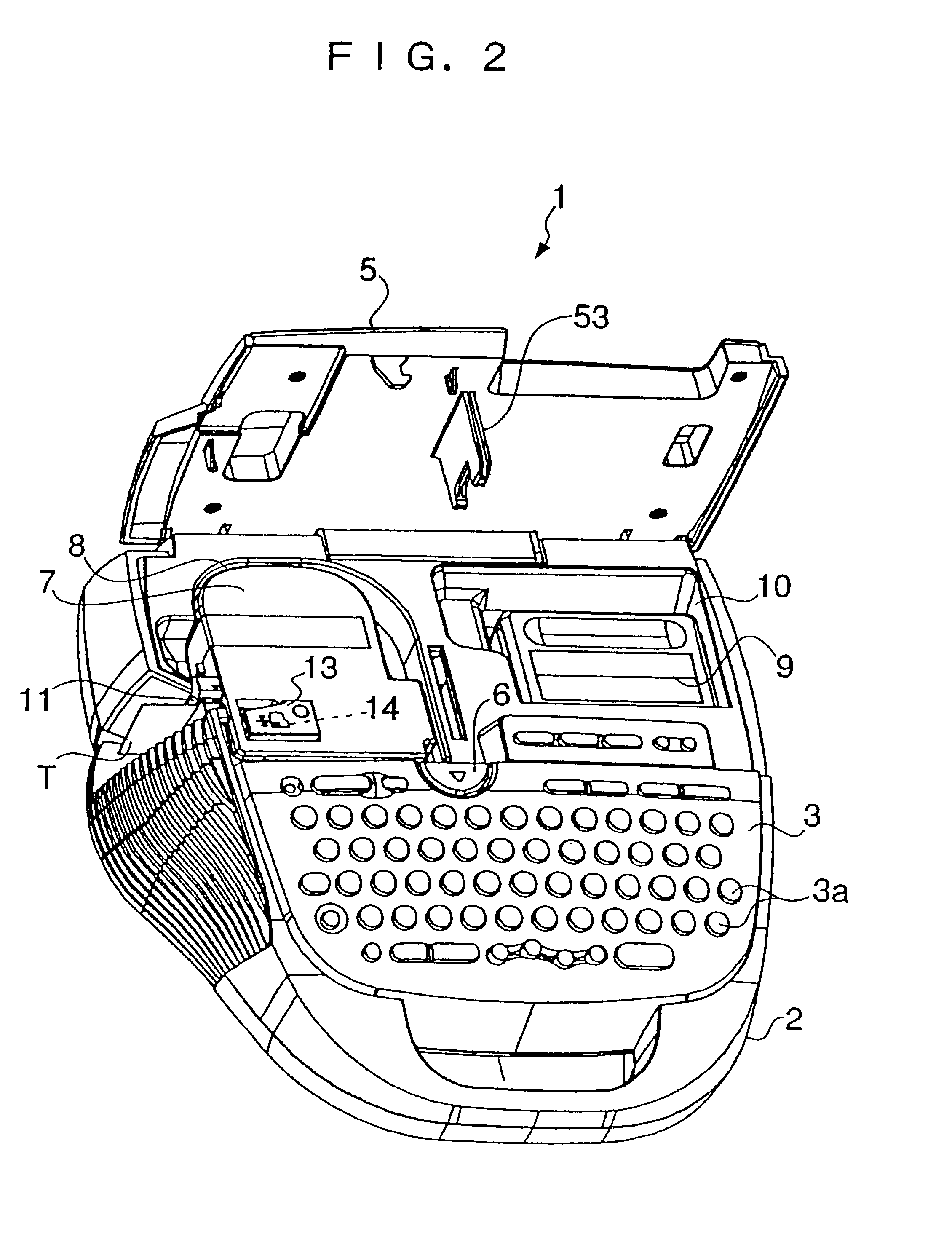
The invention will now be described in detail with reference to the drawings showing a tape printing apparatus to which is applied a tape cartridge-holding mechanism according to an embodiment thereof. The tape printing apparatus is capable of printing desired characters and figures on a strip of printing tape and cutting off a printed portion of the printing tape to a predetermined length. The cut-off piece of the printing tape is used as a label to be affixed to a document file or the like. That is, the tape printing apparatus makes a label printed with characters and figures from a strip of plain printing tape. In this case, the plain printing tape and an ink ribbon as consumable articles are provided in a state contained in a tape cartridge.

Referring first to FIGS. 1 and 2, the tape printing apparatus 1 has an apparatus casing 2 comprised of upper and lower divisional portions, and a handle formed at the front thereof. A key entry block 3 comprised of various kinds of keys 3a is...


PUM


Abstract

There are provided a tape cartridge-holding mechanism which is capable of reliably and immovably holding a tape cartridge in a cartridge compartment without spoiling the ease of mounting and removal of the tape cartridge, and a tape printing apparatus including the tape cartridge-holding mechanism. The tape cartridge-holding mechanism comprises a lid for opening / closing a cartridge compartment, at least one pair of left and right holding nails for engaging with a tape cartridge mounted in the cartridge compartment and thereby sandwiching the tape cartridge such that the holding nails press the tape cartridge against a bottom surface of the cartridge compartment, and an urging mechanism arranged in contact with at least one of the pair of holding nails, for urging the holding nail in a direction of sandwiching the tape cartridge as closing operation of the lid is carried out.

Description

This invention relates to a tape cartridge-holding mechanism for immovably holding a tape cartridge mounted in a cartridge compartment, and a tape printing apparatus including the tape cartridge-holding mechanism.Conventionally, in a tape printing apparatus of this kind, a printing tape is rolled out from a tape cartridge mounted in the apparatus, and printing is carried out on the printing tape rolled out. Therefore, the tape printing apparatus has a lidded cartridge compartment formed as a recess for receiving a tape cartridge therein, and a print head arranged in the cartridge compartment. Further, as shown in FIG. 6, the cartridge compartment 60 has a compartment casing 61 having a pair of left and right resilient holding nails 62, 62 integrally formed therewith in an erected manner. When a tape cartridge 63 is mounted in the cartridge compartment 60, the pair of holding nails 62, 62 engage with respective sloping faces 64a of recesses 64 of the tape cartridge 63 to immovably sa...

Claims


Application Information

Patent Timeline
IPC IPC(8): B41J15/04B41J3/407
CPCB41J15/044B41J3/4075
Inventor UNNO, TERUHIKOHASHIMOTO, AKIRASUETANI, TAKUYANAKAMURA, TOMOKIHORII, NOBUYUKI
Owner SEIKO EPSON CORP
Learn More