
Structure of computer CPU heat dissipation module

a technology of heat dissipation module and computer cpu, which is applied in the construction details of electrical apparatus, instruments, and casings of cabinets/drawers, etc., can solve the problems of poor heat dissipation function and insufficient ventilation of the mask housing 21

Inactive Publication Date: 2002-06-18
CHOU FARGO
View PDF16 Cites 62 Cited by
  • Summary
  • Abstract
  • Description
  • Claims
  • Application Information

AI Technical Summary

Problems solved by technology

If the discharged heat energy is large, the function of heat dissipation is poor.
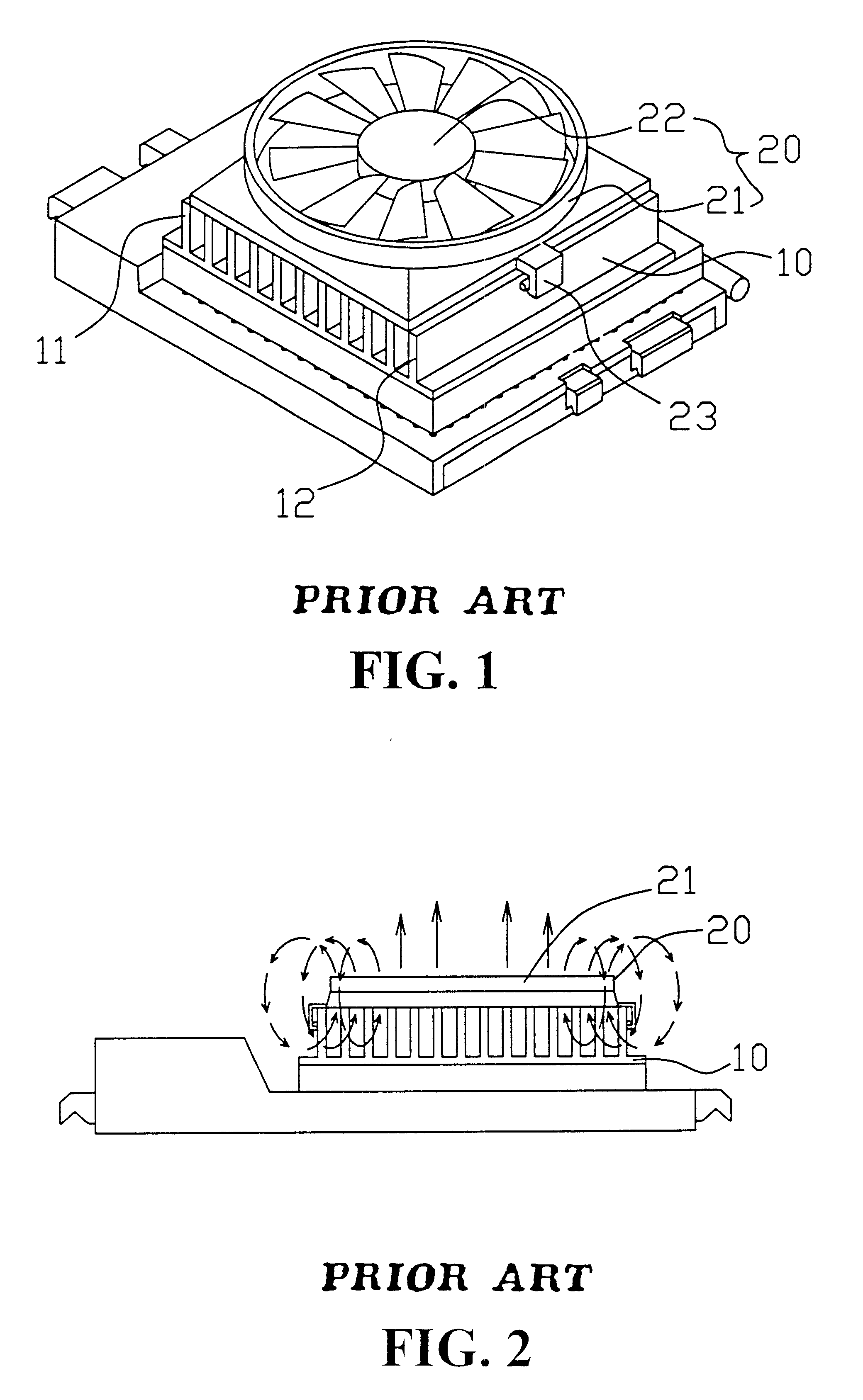
It is understood that this drawback still exists in small for the heat dissipation fin 10 with low volume of heat dissipation, and if the distance of heat dissipation is short, the ventilation at the mask housing 21 is insufficient.

Method used


Image

  • Structure of computer CPU heat dissipation module
  • Structure of computer CPU heat dissipation module
  • Structure of computer CPU heat dissipation module

Examples


Embodiment Construction

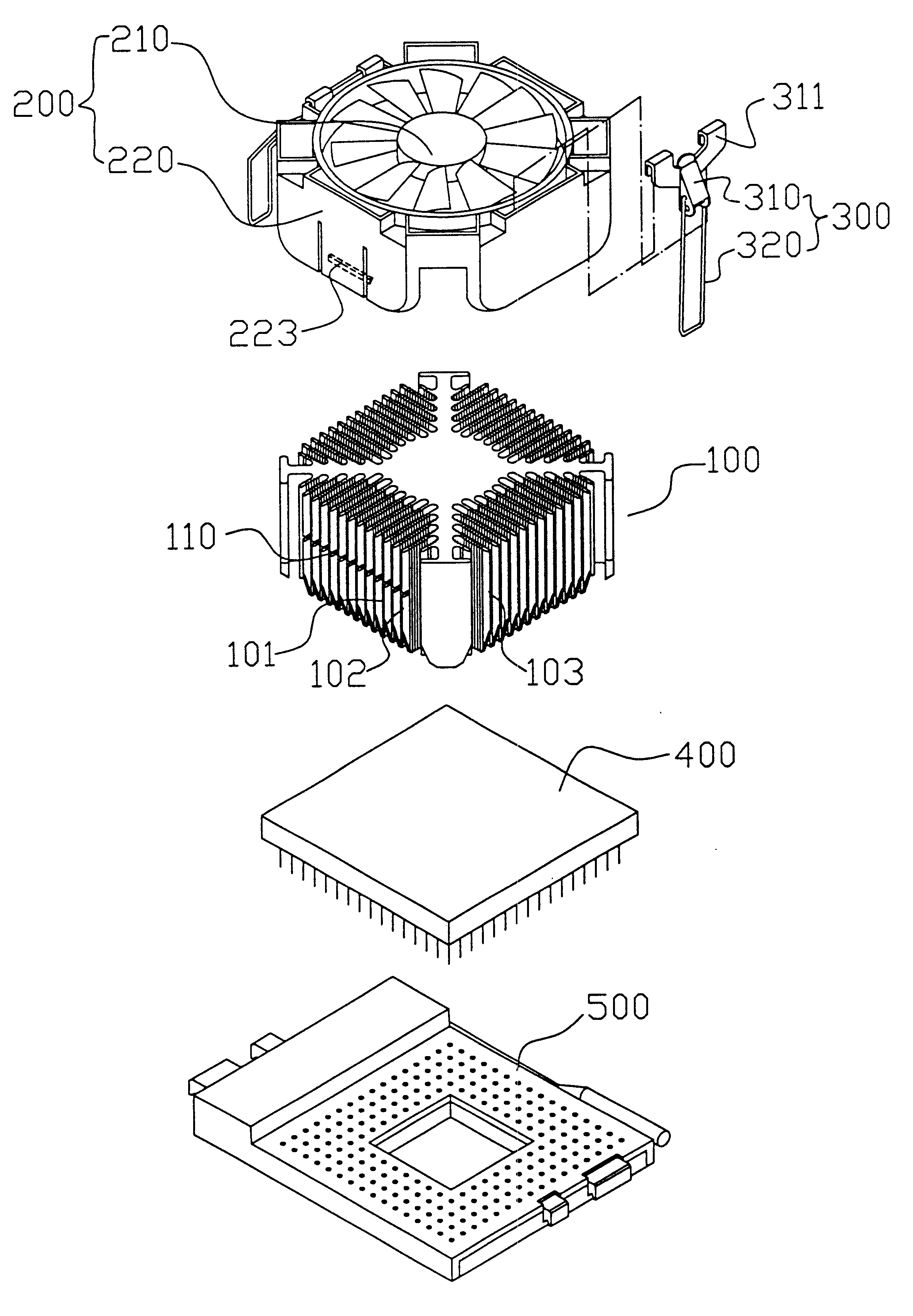
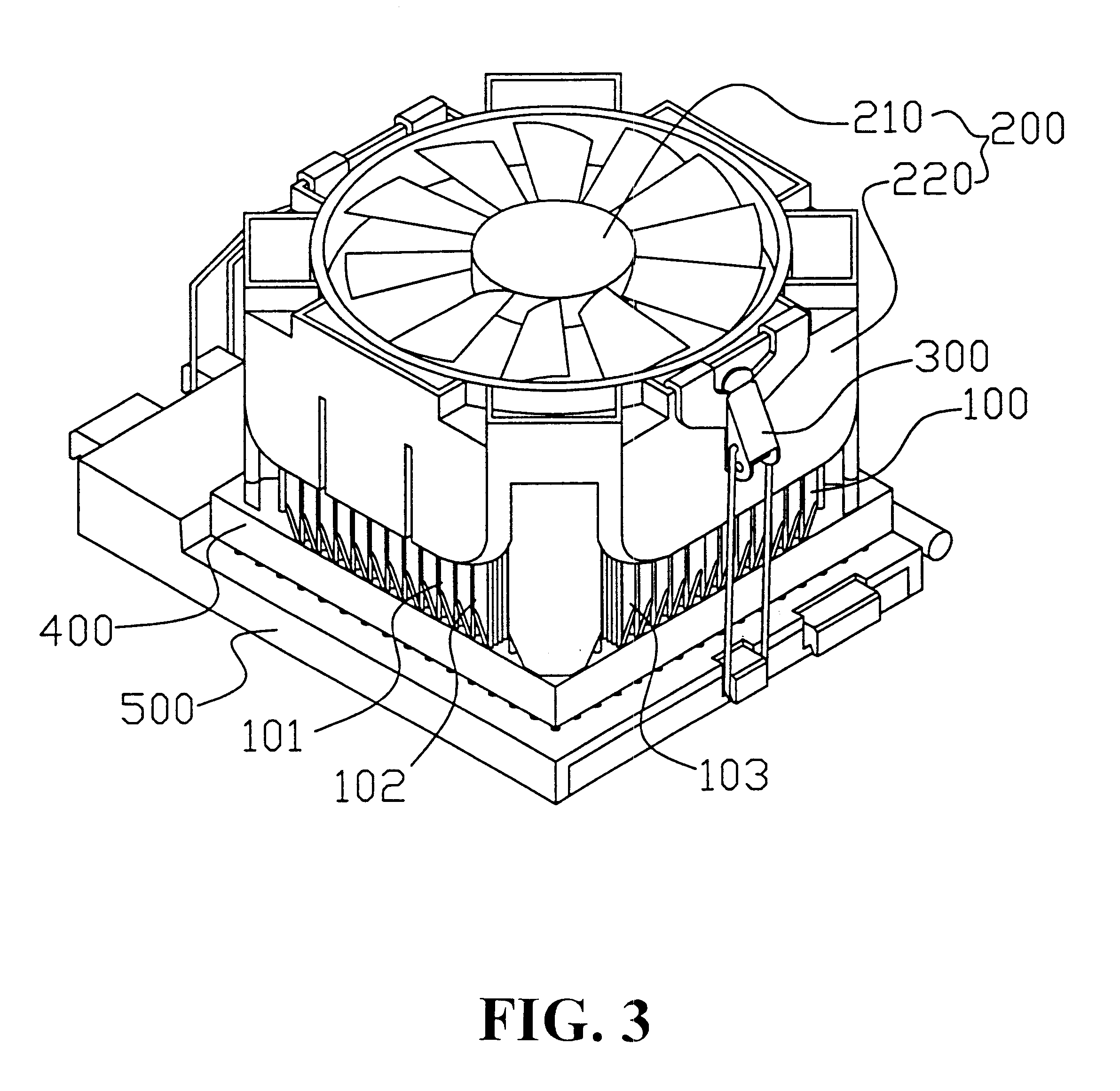
Referring to FIGS. 3 and 4, there is shown a new computer CPU heat dissipation module comprising a heat dissipation fin 100, a heat dissipation fan 200, and a pair of clipping elements 300. After the CPU 400 is mounted at a CPU seat 500, the top of the CPU 400 is stacked with the heat dissipation fin 100, and the top face of the heat fin 100 is mounted with the heat dissipation fan 200. The clipping elements 300 are used to mount the entire structure, and in particular, the heat dissipation fin 100 is a cubic structure having a height, which is approximately equal to the width and length thereof. A plurality of heat dissipation side fins 101, 102, 103 are extended toward the circumferential edge of the structure. The bottom end of the surrounding is tapered, and the heat dissipation fan 200 (as shown in FIG. 5) comprises a fan body 210 enclosed by a mask housing 220, which is unidirectional protruded. At an appropriate position within the mask housing 220, a positioning block 225 is...


PUM


Abstract

A structure of computer CPU heat dissipation module comprising a heat dissipation fin, a heat dissipation fan, a pair of fastening element, the CPU being mounted at a CPU seat and the top of the CPU mounted with the heat dissipation fin, and the top face of the heat fin being mounted with the heat dissipation fan which is then fastened by the fastening element, characterized in that the heat dissipation fin is a cubic structure having a height approximate the same as the length and width and the heat dissipation side fin is protruded toward the surrounding and the bottom end thereof is tapered, and the heat dissipation fan has a fan body enclosed a unidirectional mask housing which can exactly cover the wall of the top surrounding of the heat dissipation fin such that the fan body is stacked on the top of the heat dissipation fin, and the fastening element has one end being a fastening body, and the other end is a fastening ring, the back end of the fastening body has a suspension clip so as to fasten the top end at the two lateral wall of the mask housing, thereby the fastening body can cause the fastening ring to fasten the fastening hook corresponding to the CPU seat.

Description

(a) Field of the InventionThe present invention relates to a structure of computer CPU heat dissipation module, and in particular, a heat dissipation fan with a mask housing mounted at the external of the fan. The heat dissipation fin is a cube with a large volume of heat dissipation capacity.(b) Description of the Prior ArtThe upgrading of computer CPU efficiency is important in all computers. If the operation ability of the CPU is faster, the operation ability of the computer with this CPU will be faster. Thus, it is a trend that the speed of CPU is to be upgraded in the manufacturing of computers. However, the heat energy generated by a high speed CPU of a computer will relatively higher, and therefore, a powerful heat dissipation module has to be mounted to the CPU of the computer so as to reduce the working temperature of the CPU in order to maintain normal operation.FIG. 1 shows a conventional computer CPU heat dissipation module. This module has thin heat dissipation fin 10, ...

Claims


Application Information

Patent Timeline
Patent Type & Authority Patents(United States)
IPC IPC(8): H01L23/34H01L23/467
CPCH01L23/467H01L2924/0002H01L2924/00
Inventor CHOU, FARGO
Owner CHOU FARGO
Learn More